Power and energy measurements taken at very short or long wavelengths or at ultrafast frequencies often result in vanishingly small signal levels. It is generally the case that noise is the limiting factor in making such measurements. Noise can originate in the signal itself or in the detection system, but the first step in improving measurement quality is to minimize the noise from the environment.
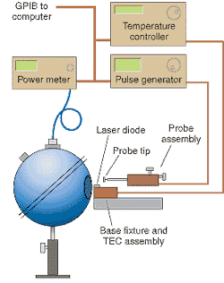
This typically includes making adaptations to the detector. Apertures and filters can be used to exclude stray light. Certain measurements, particularly in the infrared, necessitate the added cost and complexity of cooling the detector—as a rule, detector noise is cut in half by each 20°C drop in temperature. One essential accessory for measuring diode lasers and light-emitting diodes (LEDs) is an integrating sphere (see Fig. 1).
The sphere completely encloses a photodiode, which protrudes through to the inner surface, usually near the top. The inner surface is painted with a highly reflective white coating, with a baffle to shield the photodiode surface from the more direct reflections of light. The sphere captures essentially all of the light that enters the aperture, and its measurements are insensitive to the exact position of the light source or the photodiode.
Total noise from the environment can often be characterized by a 1/f dependence on frequency. For noise originating within the measurement system itself, it is often the case that the amplifying electronics make the most significant contribution. In order to minimize noise in the electronics, it is first essential to understand the sources and characteristics of noise.The nature of noise
A useful starting point is to think of each source of noise in the system as producing an individual current in the measurement circuitry. The physical origin of the noise and its frequency dependence depend on the nature of the component, as summarized in the table. Each noise source then contributes to the total noise current as an rms (root mean square) term, as follows:
A variety of parameters are used to characterize the total noise in a measurement. Perhaps the most useful is "noise equivalent power," or NEP, which is the amount of light it would take to produce a signal equal to the noise signal in the system. The NEP is related to the total noise current by the responsivity of the detector at the wavelength being measured, R(l).
The responsivity R(λ) varies a great deal from one type of detector to another; for a common photodiode it is about 0.5 A/W at visible wavelengths. So if the noise sources generate a current on the order of, say, tens of nanoamps at the signal wavelength, the signal will be competing with the equivalent of tens of nanowatts of noise power, in the range of many sensitive applications.
Speed vs. noise
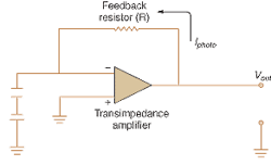
Minimizing the noise contribution in the design of detectors and instruments typically involves a tradeoff between speed vs. sensitivity and noise. This can be illustrated by considering the characteristics of a photodiode in photoconductive mode. The modern incarnation of this device uses a transimpedance amplifier as the equivalent of a feedback resistor R, while still operating in a linear region of the response curve (see Fig. 2).The speed of the detector is determined by its RC characteristics, where C refers to the internal capacitance of the photodiode junction. High-speed applications require a detector with a small feedback resistor and the smallest possible capacitance, so a large reverse bias is applied to reduce the junction capacitance. This has the effect, however, of raising the NEP by creating additional shot noise in the diode. In this case, extra care and expense is spent to minimize other noise sources in the system.
While NEP is useful in quantifying noise, the final determination of the quality of a measurement is the signal-to-noise ratio (SNR). There are several time-honored techniques to recover low-level signals, even when the SNR falls below unity. Modern digital electronics have extended the range of these techniques and simplified their implementation. These techniques rely on first knowing the sources and characteristics of the noise in the signal, and then anticipating when the signal is likely to be present.
Chopping light
When an application calls for measuring a continuous beam, a detector is chosen that typically produces a dc signal, such as a photodiode or a photomultiplier. However, the high gain amplification of weak dc signals exhibits considerable drift; moreover, the signal from any stray light or other erroneous sources is also amplified. These problems are alleviated if the continuous beam is made to produce an alternating output from the detector.
A light chopper is a simple device that illustrates this concept in a straightforward manner. The light chopper is a rotating, slotted, opaque disk that is placed in the beam path. As the disk rotates, it "chops" the beam, producing an on/off signal from the detector at a frequency determined by the number of slots and the period of the disk. The frequency is simply and precisely set by the chopper controller.
The detector output can then be multiplied by an ac amplifier, which in general is not affected by temperature-induced drift. Sources of erroneous dc signals not collinear with the signal beam are also readily eliminated. The frequency of the chopper is often chosen to be a prime number to discriminate against common ac sources, such as harmonics of 60 Hz emanating from fluorescent lighting.
The lock-in amplifier
A light chopper is often paired with a lock-in amplifier, which produces an amplified dc signal proportional to the value of an ac input signal. The term "lock-in" refers to the ability of the instrument to lock to a chosen frequency and ignore all other signals. This locked frequency is fed directly from the light-chopper controller. The signal of interest is thus the envelope of the amplitude-modulated input.
The circuitry of a lock-in amplifier is designed to perform a calibration of the input that allows it to handle amplitudes that are hundreds of times larger than the signal. This gives the instrument the ability to measure signals that would otherwise be dwarfed by noise. This feature is called "dynamic reserve" and is a measure of the instrument's ability to recover weak signals from a noisy background. The demodulator section of the amplifier is responsible for deriving the true signal from the amplitude modulation.
Since the late 1960s, the design of the lock-in amplifier has progressed from a fairly simple instrument to a microprocessor-controlled system. Matched with digital signal processing, the modern instrument has increased dynamic range and provides drift-free dc output. As a result, the lock-in amplifier is routinely used to recover small optical signals found, for example, in spectroscopy or in experiments that require cryogenic cooling.
Better on average
If the input to be measured is, say, a brief pulse, or has some other form that cannot be amplitude-modulated, then something other than a lock-in amplifier is needed to recover the signal. A general approach is to sample the waveform of the signal at regular intervals, store each sample, and add successive waveforms to the total. Random sources of noise will tend to cancel in the summation, while the signal will be enhanced.
In principle, the improvement factor is equal to the square root of the number of samples. So, for example, summing 100 samples will improve the SNR by a factor of 10. An instrument with this sample and sum capability is called a signal averager. The two most common types of signal averagers are the boxcar averager and the multipoint averager.
A boxcar averager monitors one discrete point in time of a repetitive signal and averages that point over many cycles before storing its value. A different point in time is then selected, and the sample and average process is repeated for the same number of cycles as for the first point. In this way a boxcar averager steps across a waveform at discrete points to build up an average representation of the input signal. Random sources of noise tend to cancel themselves out in the process, much as they do for the light chopper.
A multipoint averager uses a detector array and digital memory to save the entire waveform of each sampling cycle. These instruments are thus better suited to capturing short-lived signals or providing data for some types of spectral analysis, such as time-domain reflectometry. Their time resolution is typically on the order of a few nanoseconds. The boxcar averager, while slower overall in data capture, has picosecond resolution and so is preferred for capturing a single point in time—for instance, a single peak in the spectral output of a repetitively swept monochromator.
Modern instrumentation
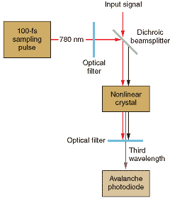
The noise levels of modern high-speed optical sampling instruments are largely dominated by the thermal noise in the amplifier circuitry. Thermal noise remains constant as signal strength rises or falls, so the SNR figure suffers at low signal levels. Optical instruments from Agilent (Palo Alto, CA), produced for the development of 40-Gbit/s networks, circumvent the thermal noise problem with a novel use of nonlinear optics.
The signal to be measured is frequency-mixed in a nonlinear crystal with the output of a high-speed optical reference (see Fig. 3). The noise level is now defined by random effects in this frequency-mixing process, characterized as shot noise. Unlike thermal noise, shot noise does vary with signal level. When the signal level falls, so does the noise. The SNR for this instrument is a function of the input level.Today's instruments make full use of modern electronic design, including large volume digital memory and high-speed circuitry made of gallium arsenide instead of silicon. These sophisticated designs use the same conceptual building blocks of signal processing, such as modulation, sample-and-hold, and so forth. In addition, a modern instrument needs the capacity to measure the spectral components of the signal.


