For most applications, the size to which a laser beam can be focused is as important a consideration as the laser output power. Frequency doubling, for example, depends on the square of the intensity of the primary laser. The depth of a hole drilled by an industrial laser depends on the laser intensity and the hole diameter is proportional to the spot size.
Maintaining a consistent beam profile is usually important whether the beam is focused or not. Ophthalmic surgery uses a beam with a flat cross section (a "top hat" profile) that must remain constant during the procedure. All of these applications require a laser designed to produce a consistent and well-characterized beam.
To be propagated over a long distance, a laser beam needs to have the lowest divergence possible. Telecommunications combines this requirement with a need to control the spectral content of the beam to ensure data quality. Whenever low divergence or small spot size is required, a laser with TEM00 output is specified.
What is TEM00?
It is useful to think of the light inside of a laser as formed of standing waves with distinct vibrational modes. Only a small number of modes will exist in the transverse direction. The fundamental transverse mode is designated as TEM00, where the "00" indicates no nodes appear in the beam profile. "TEM" stands for "transverse electromagnetic" and refers to the form of the standing waves. The TEM00 mode is mathematically described by the familiar bell-shaped Gaussian curve.
Higher-order modes are formed by multiplying the Gaussian by a polynomial with an exponent that corresponds to the order of the laser mode. These higher-order modes describe the number of nodes that appear in the beam—the TEM11 mode of a rectangular resonator, for example, will appear to have a dark cross in the middle of the profile. Higher-order modes add frequency components to the fundamental mode.
The Gaussian function extends to infinity in the radial direction, leaving open the question of the beam diameter. Measuring a laser beam diameter has been compared to using calipers to measure the width of a cotton ball. The accepted definition is the diameter at which the intensity has fallen to 1/e2 (13.5%) of its peak value in the center.
The 1/e2 definition works well for Gaussian modes, but is not useful for other profiles. In these circumstances the diameter is calculated using the "second moment" algorithm, a combination of integrals similar to a formula for calculating an rms (root-mean-square) value. The second-moment calculation should be used cautiously because it gives heavy weight to the edges of the beam.
Measuring beam size
Early means of determining a profile were essentially visual, such as examining the pattern of a continuous-wave (CW) beam on a lab wall or the burn marks made by a pulsed infrared beam on photographic film. It is an indication of the difficulty in measuring high-power pulses that visual techniques are still used. Instruments that measure beam profiles (profilometers) either use CCD cameras, or else scan a slit or knife-edge through the beam.
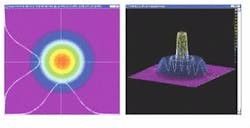
A CCD camera is a user-friendly system capable of instantly displaying the entire beam profile. It can be used with both CW and pulsed beams. The intensity distribution of the profile can be displayed as either a two-dimensional (2-D) or three-dimensional (3-D) contour plot. Charge-coupled-device cameras are superior for measuring elliptical beams, and their real-time capability is useful in production control (see Fig. 1).
The limitation of this instrument is its resolution, set by the pixel size of the CCD array. Currently this can be as small as 10 µm, but a pixel size closer to 20 µm is more typical. In addition, most beams must be attenuated to avoid saturating the array, and the attenuating element introduces some degree of distortion, although a new CCD array using a diamond substrate appears robust enough to measure short-wavelength pulses directly (see Laser Focus World, May 2000, p. 265). Finally, a CCD camera is not the first choice if second-moment calculations are important—the signal-to-noise ratio of the CCD array decreases at its edges.
Scanning profilometers
These instruments scan a slit or a knife-edge through the beam and correlate the measurement from a detector behind the aperture with the aperture position. Different detectors can be positioned to allow these instruments to work at almost all wavelengths. Resolution, which is limited by diffraction from the scanning edge, is on the order of the wavelength of the beam.
A scanning slit masks most of the beam from the detector, eliminating the need to attenuate the beam. It is important to choose the correct slit size for the beam diameter—a slit too wide will make the measurement appear smaller than the beam itself. The slit should be no wider than one-third of the beam, and preferably narrower.
Knife-edge profilometers have a resolution as fine as 100 nm. As the blade moves across the beam, the detected signal decreases to zero and the measurement is differentiated to obtain the profile. Some systems use the same algorithm as that used in medical tomography for MRI and CAT scans to calculate the profile. However, scanning systems are not useful for pulsed measurements.
Whatever instrument is used, the beam should be measured at a distance from the laser sufficient to allow spontaneous emission and other light noise to diverge and not pollute the measurement. Lasers that produce the profile for which they are designed, free of aberration and the like, are said to be "diffraction limited." This does not mean, however, that their output is TEM00.
Raleigh range and divergence
Gaussian wavefronts start out as planes at a location called the "beam waist" (sometimes located inside of the resonator). The wavefronts become increasingly curved as they propagate from the waist until they reach their smallest radius, after which they flatten out. The distance from the waist to the location at which the wavefront is most curved is called the Rayleigh range.
The region between the beam waist and the Rayleigh range is the near field. In the far field the beam diverges in a cone with (nearly) straight sides. Divergence is always specified in the far field, which is usually chosen to begin around 10 times the Rayleigh range.
The distance from the laser to the far field can be meters, an inconvenient distance for measurement, so a lens is often used to focus the beam, thereby forming a new beam waist. The divergence is then the beam size at the lens divided by the distance from the lens to the focus. It is important that divergence is measured in the far field, or calculations for beam parameters will be incorrect.
The propagation of a Gaussian beam is fully specified by its beam waist and its divergence. For an ideal TEM00 beam, the product of the beam waist ω0 times the divergence angle θ0 can be expressed as
ω0θ0 = λ/π
This implies that a Gaussian beam can be characterized by measuring its beam waist and its diameter at one other location. In practice it can be difficult to locate the beam waist. Modern instruments determine beam parameters from measurements taken at multiple locations.
Non-Gaussian beams
All lasers deviate to some extent from the Gaussian ideal. Many high-power carbon dioxide (CO2) lasers emit beams with rectangular profiles; diode laser arrays produce a beam that does not appear to come from a laser at all. Even lasers operating in TEM00 mode truncate the beam because of the limiting aperture in the cavity, which results in fringes in the near field.
There are limitations in choosing a beam for an application based on its correlation to a Gaussian profile. In fact, a high correlation to a Gaussian fit can be achieved by a beam that contains only higher-mode components (see figure). The spot size to which such a beam can be focused differs significantly from what one might expect.When the beam deviates from Gaussian, the product of the beam waist times the divergence must be increased by the "quality factor" of the beam, M2. The product of beam waist and divergence becomes
ωθ = M2λ/π
M2 represents how many times wider the focused spot is than the theoretical minimum. An M2 of 2, for example, indicates that the focused beam will be twice the ideal minimum spot size, and so this beam will have only 25% of the intensity of a fundamental beam of the same power. M2 values for beams of the highest quality are <1.1, while values of M2 for multimode lasers might be around 4.
Measuring M2
The wide applicability of M2 has led the ISO to adopt it as the standard for beam quality. M2 profilometers form a new beam waist with a lens and take measurements before, within, and after the waist. According to the ISO standard, the lens must be stationary and the detector move to take the measurements. In addition, the calculations must be based on the second-moment algorithm.
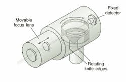
For well-collimated beams, an instrument with a fixed detector and a variable lens will provide a reliable approximation of M2 (see Fig. 2). This simplifies the design of a scanning mechanism. Such instruments can provide precision measurements in applications that employ well-controlled laser sources.Astigmatism
Another parameter that relates to diode lasers deserves mention. Most diode lasers have rectangular output facets that produce elliptical beams. In addition, the cross section of the beam in the plane vertical to the direction of propagation has a waist and divergence different from that in the horizontal plane—that is, the beam is astigmatic.
The astigmatism in a focused beam must be corrected for the beam to be useful—a cylindrical lens tilted in the direction of propagation can do the trick. The "astigmatic distance" is the distance between the two different foci, which must be eliminated in the correction. Instruments based on CCD cameras are well suited to determining the astigmatic distance.
Next month's article in this series discusses the measurement of polarization.
OMISSION
In "Back to Basics: Semiconductor Lasers" (May, p. 145), Fig. 1 on p. 149 represents technology patented by Alcatel. The author wishes to acknowledge the assistance of Alcatel in preparing the illustration.


