As virtual reality (VR) refers to the creation of a separate world, a device that immerses the user in VR requires a near-eye display adapted to the human vision system without the need to be able to see through the display. With augmented reality (AR) and mixed reality (MR), the virtual image overlays (AR) or interacts with (MR) the real world. Both AR/MR require display technology that allows the user to see the real world and the virtual image in parallel.
The optical design of an appropriate device is among the most significant technological challenges associated with AR. At the heart of the AR device is the optical combiner, which brings together the real-world image with the virtual image generated by a display or projector. Although the form factor of these combiners, in many cases, has rarely been suitable for daily consumer use.
Waveguide technology offers a potential solution to this problem, whereby flat substrates made of optical-grade glass serve to guide the image parallel to the waveguide’s surface while simultaneously allowing light to pass through perpendicular to the waveguide’s surface (see Fig. 1). A sizable portion of performance-defining parameters depend on the waveguide material and its specifications, such as refractive index, specific density, transmission, homogeneity, flatness, warpage, etc.
The maturing AR industry needs to consider lifetime and reliability issues often tied to product robustness and processing yield. The robustness of glasses is a result of the way they are processed. Usually, most concerns regard eye safety for the end consumer. Nevertheless, glass fracture during processing also has a considerable risk of affecting other parts in the production line. For this reason, it is essential to have a singulation process that yields a high and predictable breaking strength and maintains the relevant component characteristics over an extended production run. Only then can the manufactured products be commercialized in the end customer market.
SCHOTT AG and 3D-Micromac AG have teamed up to better understand the process fracture strength interaction of glass used for AR eyepieces. The final goal is to provide AR device makers with a complementary material and equipment solution that provides a reliable and scalable solution for cost-effective waveguide manufacturing, from lab scale to mass production.
Methodology and experiments
Laser process and setup. The development started with a decision to deploy a mass production-proven cutting process. Laser modification cutting is a standard and recognized production process used for years in the display industry and thus was selected.
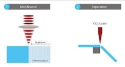
The first step is to modify the glass (filamentation) along a pre-determined curve (the intended break line) and through the entire material thickness using pico- or femtosecond laser pulses (see Fig. 2). Each point of modification is created by the local impact of a single laser pulse or pulse bursts. Bursts typically consist of numerous individual pulses within a very narrow timeframe and effectively interact at a single modification. For the chosen glass, a large range of ultrashort-pulse lasers (with pulse durations from 350 fs to 20 ps) and pulse parameters were investigated to find a reliable and controlled modification process. The number of pulses was altered from a single pulse up to 8 pulses per burst and the accumulated burst energy, from 80 to 270 mJ. Additionally, the pitch (distance of the individual modifications along the cutting path) was varied between 1 and 10 µm.
Next, a secondary process step is required to separate the glass along the break line. For freeform geometries, the required stress is typically introduced by exposing the modification and its surrounding material to a CO2 laser.
All results in this experiment were realized on SCHOTT RealView glass wafers with a refractive index of 1.8 (RealView 1.8) and a thickness of 700 µm.
Strength measurement. The strength of the glass was measured with a standard 4-point bend test setup1-3 with sample sizes of 45 × 44 mm. The bending test was performed along the 45 mm side of the specimen. However, the standard 4-point testing methodology has limits in that as soon as the displacement of the center point equals or surpasses the thickness of the specimen, the applied simplified plate theory generates inaccuracies and corresponding absolute results. A FEM analysis was conducted, and the results were used to adjust the measured force to stress conversion. All specimens were checked regarding the type of fracture. Samples with fracture origins in the plane were disregarded.1, 2
Statistics and experimental design. 3D-Micromac conducted a set of statistical experiment designs with variations of the laser parameters described above. The four response variables chosen were characteristic value and Weibull modulus for the laser’s entrance and exit sides. From a phenomenological standpoint, it was expected that the two sides would behave differently. As mentioned above, it is crucial to understand and control these differences to set up a stable and reliable process. The experimental design reflected this aspect by separating and testing the two sides of the specimen separately. Initially, a rough parameter screening was carried out, refined, and verified afterward.
Experimental results
The purpose of the first screening design (screening run 1), reaching over a vast range of parameters, was to find a model that predicts the response variables with the chosen parameters. After several experiment sets, it was possible to approximate a reasonable model (r2=0.97) for the laser entrance and exit side.
After determining the most favorable process window, the engineers conducted a more granular experiment (screening run 2) to find the sweet spot in strength values. Again, the investigation reached a solid model fit, although the model predicted a significant difference in characteristic values between the entrance and exit sides. Thus, the investigating parties decided to optimize the process to where the entrance and exit sides exhibit the same high-strength value.
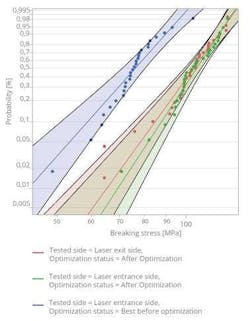
The validation results revealed multiple details. Firstly, the bending strength of the glass (see Fig. 3) was strengthened by more than 30% when using the new laser modification process (blue line) compared to previous results (red/green line).
Secondly, these results showed that the designed model of the laser process could predict and, by deploying appropriate laser parameters, also target a desired outcome in terms of characteristic value and modulus. That becomes apparent by the similarity of the red and green distributions in the figure, representing either independent entrance (green) or exit side (red) measurements.
Thirdly, the results proved that a stable, mass-production-ready laser process had been developed. The consistent findings and reproducible results from the model allow for extrapolation and a reliable prediction on variables such as yield and stability.
After validating the results of the new laser cutting process with a high degree of reproducibility, the next step was to implement the process into a machine concept suitable for mass production. An essential aspect of the machine concept was ensuring that other components integrated into the process flow (e.g., material feed and handling tools) did not negatively influence process parameters.
Ongoing tests have shown that the settings in the model were easily transferable to other relevant glass types used for AR eyepieces. That, in turn, indicated that the model is an essential basis for optimizing the process in an application-specific and efficient manner.
Process integration into a scalable mass production platform
Modular equipment. Although many AR customers are still in the early phase of product development, the team decided to design an upgradable modular laser system (microPOLAR) due to AR’s clear path to mass production. The system’s base is an industrial-proven and mature transport system, which offers the possibility to integrate different process, handling, and quality inspection modules to provide users with a high degree of flexibility.
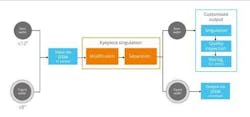
The laser system can process either bare wafers or wafers applied on adhesive tape (see Fig. 4). The process modules for separation can be supplemented with input and output handling. Furthermore, several process modules of the same type can be ordered in parallel to increase throughput, for example, at the slowest sub-process step.
The customized multi-carrier system, as well as the integrated laser sources, are already industry-proven. The system design and the workflow were co-developed and approved by SCHOTT. As the systems are fully up- and downgradable, customers can retrofit fully automated handling units or additional working stations on site. The loading process is carried out by SEMI-compliant standard wafer handling (EFEM).
The output module was designed with special attention to maintaining the breaking strength of the eyepieces since even the slightest damage to the edge of the eyepieces can negatively impact the yield and the lifetime of the devices.
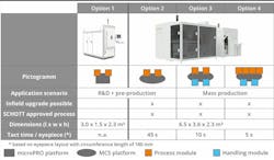
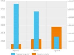
Configurations and cost overview. Figure 5 shows an overview of system configurations. Option 1 is a fully flexible R&D solution for the process development and product testing phase. Options 2, 3, and 4 are based on the abovementioned multi-carrier platform, which is up- and downgradable depending on customer needs. Since the products/eyepieces are installed in devices sold on the B2C market, production costs play a significant role. A fully equipped laser machine with four process modules in line can produce one eyepiece in approximately five seconds. That leads to a maximum annual throughput of roughly five million eyepieces.
Throughput and yield have a direct impact on the cost of ownership. Fully equipping the machine can reduce production costs per eyepiece by at least 80% (see Fig. 6).
Conclusion
By combining their expertise in material science and equipment building, SCHOTT AG and 3D-Micromac AG were able to significantly advance the understanding of high-strength and high-throughput cutting of high-index glass used in AR eyepieces. The generated model predicts the characteristic value of the strength of each side of a cut specimen. This model allows the deployment of an optimal laser source and laser parameters to develop a stable, mass-production-ready process, creating significantly higher and equal strength on both sides of the glass. In addition, the model allows for tailoring the process to the application’s specific strength needs.
Furthermore, a modular and scalable machine concept that supports throughput from lab to mass production was presented. The modularity of the concept ensures that the stable and mass-production-ready process is already fully implemented in the lab-scale form of the equipment. In addition, this modularity concept avoids the high capital cost associated with purchasing a separate mass-production-ready system since higher throughput can be attained by adding more modules in the field.
ACKNOWLEDGMENT
RealView is a registered trademark of SCHOTT AG.
REFERENCES
- J. Herrmann, Fraktographie, TSA-Z Standard operating Procedure AAW_ZL_P-002-01 (Nov. 8, 2017).
- 2. G. D. Quinn, Fractography of ceramics and Glasses, NIST Special Publication 960-16e2 (2016).
