GEORGE TREUSCH, TOBIAS KOENNING, and BEN SHELEF
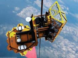
Power beaming—the wireless transmission of energy from one location to another—has come a long way since Nikola Tesla’s experiments on couple-tuned-circuit oscillators. Although wireless power beaming is less efficient than using a conductor, it is the only way to power remote locations when laying power lines is not feasible, such as when a vehicle climbs 100,000 km into space from the Earth’s surface—also called the space elevator (see Fig. 1).
In 2004 the Spaceward Foundation asked the Centennial Challenges office of the National Aeronautics and Space Administration (NASA; Washington, D.C.) to conduct two prize technology challenges on the core technologies that make up the space elevator: very strong tethers and improved power-beaming systems.1 While NASA’s interest in the two competition topics stems from their usefulness in other fields, the two challenges under the “Elevator:2010” umbrella were silently approved at the highest level. The goals in both challenges are incremental technology development, coupled with public awareness and advocacy of the space-elevator concept.
For the 2007 power-beaming challenge of 100 m in 50 s, leading competitors—including returning champions from the University of Saskatchewan (Saskatoon, SK, Canada)—chose near-infrared lasers as a power-beaming source because of the material response of the silicon (Si) and gallium arsenide (GaAs) photocell receivers used by the competing teams, as well as the power density. The field of power-beaming applications is wider than the space elevator, however, so other wavelengths may prove more appropriate for different applications.
While the power (1 MW), beam requirements (TEM00), and transmission length (100,000 km) for the final space elevator far exceed the current technology capabilities, we supplied the best performer in 2007 with a power-beaming source on very short notice (three weeks), using a new modular diode-laser-based power beamer that is applicable for both terrestrial as well as spaceborne applications.
Power-beaming challenge 2007
During the 50 and 100 m challenges of 2005 and 2006, spotlights and sunlight were the sources of choice for the power-beaming challenge. But in 2007, participants decided to include lasers to try to achieve the 100 m lift in the required 50 s; previous attempts in 2006 with noncoherent sources had not been able to achieve the required climb rate.
In 2007, the competing teams used Si- as well as GaAs-based photocells with an extended absorption spectrum to accommodate diode-pumped solid-state (DPSS) lasers with wavelength above 1 µm—the expected source of choice for the leading competitor because of its superior beam quality and power density.
The teams determined that the lift of 100 m within 50 s would require source power levels between 5 and 15 kW. Compared to diode lasers, fiber and disk lasers offer superior beam quality with a beam-parameter product (beam radius × divergence) of less than 10 mm × 1 mrad. Assuming a minimum photovoltaic panel area of 1 m2, the power-beaming limit for the DPSS laser would be approximately 2.5 km using optics of 100 mm in diameter or smaller. Diode lasers, offering a greater beam divergence at the source—typically 6 mrad in the fast axis by 20 to 30 mrad in the slow axis—are limited to 1 km with the same optics and a 1 m2 photocell as a receiver. Larger optics and panel areas would proportionally increase the power-beaming distance. However, DPSS lasers are more expensive and offer less than half (30%) of the electro-optical efficiency of laser diodes (70%). In the end, problems with a fiber-laser supplier and the higher costs of DPSS lasers worked in favor of DILAS, which delivered a 10 kW laser-diode power-beaming source for the University of Saskatchewan team.
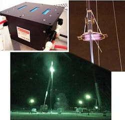
We built the 10 kW diode-laser module based on our water-cooled E-series platform. The design challenge for the module started with the selection of the most appropriate semiconductor structure for a power level greater than 100 W per bar and the capability for a divergence of 6 mrad in the fast axis and less than 30 mrad in the slow axis. This power level was achieved by combining three stacked arrays of 30 diode bars with an output power of 3.5 kW each (see Fig. 2). Each bar has its own fast-axis collimation lens and slow-axis collimation-lens array attached to the bars’ heat sink. Also included in the housing is the first set of macro lenses for a variable beam expander to match the beam size with a second set of motor-driven, external macro lenses that, when combined, match the output beam to the panel size as it climbs to 100 m. This optical design results in 95% beam overlap of each of the three stack beams at the 1 m panel at 100 m. The remaining 5% is due to the 5 cm center-to-center spacing of each diode stack in the source enclosure, which is transmitted upward to the photocell through the unified set of motorized optics.Beam divergence is critical to long-distance power beaming applications. To achieve the 6 mrad fast-axis divergence from the diode bars, the diodes needed to have a very low “smile,” which refers to a bend in the semiconductor material at the heat sink that can act as a multiplier of beam divergence. With a smile of less than 0.5 µm coupled with a reproducible lens attachment process (both developed by DILAS), the diode stack exhibited a total fast-axis divergence of 4 mrad while maintaining more than 95% of the laser power. To achieve the 30 mrad slow-axis divergence at the diode-laser bar, we matched the slow-axis collimator lens to the emitter size and divergence. The final slow-axis divergence of the beam was reduced to 6 mrad by expanding the beam by a factor of 5.
Although the USST team won the day, it missed the challenge by 2 s, taking 52 s to climb the 100 m. Hopefully, that will be rectified later this year. We are in discussions with more than five competing teams for the 2008 challenge, which increases the vertical lift required by a factor of 10, to 1 km, and the lift speed to 5 m/s.
Optimized design for 2008 challenge
The new design for the power beamer considers various approaches from different teams using low-cost Si- or highly advanced GaAs-based photovoltaic (PV) cells. Material choices, PV cell, and beam characteristics are up to the competing teams; the challenge simply sets the distance and minimum average rate of climb. Each team is likely to have its own approach with power-beaming systems ranging from 2.5 kW to values above 10 kW.
The wavelength for the power-beaming sources will likely be between 800 and 980 nm. High-power diode lasers have efficiencies greater than 60% and power levels greater than 100 W per 10 mm bar. It is a happy coincidence that Si and GaAs photocells are more efficient at this spectral range compared to wavelengths above 1 µm, which is the spectral domain of fiber and disk lasers.
One method to increase the brightness and power of the power beamer is to use dichroic mirrors to coarsely multiplex common laser diodes at wavelengths of 808, 880, 915, 940, and 980 nm. However, an optimized system must consider the response of the PV cell material. Because the PV cell material choice (Si or GaAs) is unknown at this point, we have decided not to use wavelength multiplexing in the initial 2008 power-beamer demonstration module. The basic unit will consist of two, 12-bar stacks at a single wavelength with a total output power of greater than 2.5 kW.
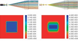
Other industrial technologies, such as polarization coupling, beam interleaving, and fast- and slow-axis collimation, can generate a beam with an exit aperture of 100 × 100 mm2 and a minimum divergence of 1 mrad in both directions (see Fig. 3). By carefully adjusting the distance between the exit lens and the inner lenses the beam size can be matched to a 1 m2 size in all distances up to 1 km. Wavelength multiplexing can be used as the next step to get to the ultimate brightness and achieve even higher altitudes.The 2008 design will also integrate the motorized optics that control the beam divergence into the base unit, and correspondingly, the beam size at the PV panel at variable distances. The power on the panel can be increased by adding more units to the power beamer; laser beams from the individual units will overlap at the PV panel with a small offset correlated to the stacking arrangement and the dimensions of the unit. Each unit has dimensions of 110 × 110 × 450 mm3 and needs a maximum current of 110 A and 46 V to be operated at 2.5 kW output power. Multiple units can also be operated in serial mode, multiplying the voltage by the number of units. For best performance, a minimum water flow rate of 6 l/min per unit is required. The proposed design is not limited to power-beaming applications, as the spot size within the beam expander is as small as 0.25 × 0.25 mm2, allowing the output to be coupled into a 400 µm fiber (with numerical aperture of 0.2) for a variety of industrial and scientific applications.
REFERENCE
1. B.C. Edwards and E.A. Westling, The Space Elevator: A Revolutionary Earth-to-Space Transportation System, publisher BC Edwards (2003).
GEORGE TREUSCH is vice president and general manager and TOBIAS KOENNING is a product engineer at DILAS Diode Laser, 9070 South Rita Rd., Suite 1500, Tucson, AZ 85747; e-mail: [email protected]; www.dilas.com. BEN SHELEF is cofounder and leader of The Spaceward Foundation, 725 N. Shoreline Blvd., Mountain View, CA 94043; www.spaceward.org.


