Optical monitoring of the state of the injection mold during operation of the injection-molding machine allows for nonstop monitoring of the process of casting plastic products.
Any process of casting plastic parts includes four operations: closing the moving and stationary parts of the mold, the process of forming the product, separating the mold parts, and pushing the castings out of the matrix. After this, before the next cycle of pouring plastic material into the injection mold, it is necessary to determine whether there are any pieces of plastic remaining inside the mold.
Automation via optical tracking system
To automate this process, it is necessary to use an optical tracking system, which should analyze the state of the forming surfaces inside the injection mold. Ideally, it is necessary to check the working surfaces of dies, punches, and ejectors of plastic products. Considering that all of these injection mold parts have polished working surfaces with mirror roughness, they are capable of reflecting incident rays of light with a high reflection coefficient of 80% to 95%. This circumstance allows the use of optical tracking systems built into the injection mold to monitor the condition of the working surfaces directly during the casting of products—at the moment the injection mold is separated.
To obtain complete information about the state of the working surfaces of the molding matrices and punches, it is necessary to illuminate them at the moment of detachment of the injection mold and analyze the image.1, 2 If the image has a reduced brightness or dark spots, it means the casting or part of it was not pushed out of the socket. In this case, before a new cycle, it is necessary to clean the working surfaces of the mold.
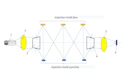
In general, the optical circuit for monitoring the position of castings in an injection mold is shown in Figure 1, and you can see the optical schematic of tracking systems for a three-cavity injection mold. The optical scheme is designed to consistently illuminate when the injection mold is open—at the moment of pushing out the castings all the punches and matrices of the injection mold. The circuit also includes the optical elements necessary to obtain an image: light source (1), condenser (2), orienting prisms (3 and 4), focusing lens (5), and radiation receiver (6). Figure 1 corresponds to the open position of the parts of the injection mold—at the moment of ejecting the products from the dies.
The optical system is constructed to consistently illuminate all working surfaces of the dies and punches in the injection mold. If a piece of casting remains in one of the nests after pushing out the products, then the amplitude of the signal from receiver 6 will show that the injection mold cannot be closed, otherwise the matrix or punch will break due to the impossibility of closing the movable and stationary parts of the injection mold.
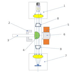
Beyond monitoring the state of the punch dies during the working cycle of producing castings, it is also necessary to ensure the ejection of products from the injection mold—castings should not hang on the ejectors. If this happens, the injection mold cannot be closed to produce new castings. Therefore, in this case, it is necessary to integrate an additional channel into the optical tracking system, which would monitor the condition of the outer edges of the injection mold ejectors. Figure 2 shows the optical design of such a channel.
The tracking system shown in Figure 2 includes illuminator (1), mold matrix (2), product ejector (3), castings (4), punch plate (5), punch (6), radiation receiver (7), and the combination of plane-parallel plates and prisms (8). Prism element 8 has a dual purpose: it reflects light on the side surfaces and transmits light through the upper and lower surfaces.
This new optical method for monitoring the condition of injection molds during the production of plastic parts makes it possible to prevent the parts of the injection mold from closing if the castings are not coming out of the nests, since this method is based on the reflection of light from the polished (working) surfaces of the dies and punches and the transmission of rays through the edges of the ejectors. This optical control method enables automating the manufacturing process of plastic products, which is especially important in the mass production of parts from plastic materials.
REFERENCES
1. L. N. Andreev and L. Ryzhikov, Instrumentation Engineering, XXXI, N8 IFMO (1988).
2. L. Ryzhikov, Plastics, N2 (1991).

