HELGE VOGT
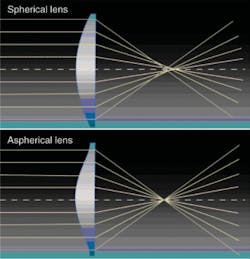
Spherical aberration and distortion in lenses for optical devices, such as cameras, is a long-standing problem that has often been addressed through the use of multiple lenses or lens arrays (see “What is spherical aberration?”). As digital imaging devices have gotten smaller over the past few decades, however, the weight and size of spherical-lens arrays have become an issue. As the demand for digital cameras and camera phones continues to grow, it becomes increasingly important to fabricate smaller and lighter lens arrays.
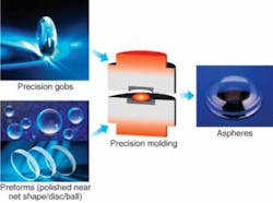
Aspheric-lens arrays require fewer elements than spherical-lens arrays to provide high-quality images. Unfortunately, the traditional aspheric production method involves polishing spherical lenses down to aspheric dimensions, which does not lend itself to economical mass production. In the 1980s, however, manufacturers began to use a new process to mass-produce aspheric lenses: high-precision optical-glass molding (see Fig. 1).
Precision molding makes large-scale production of aspheric lenses economically viable, bringing high optical performance to the smaller, lighter packages increasingly demanded in digital photography and even for industrial optical applications. Economical mass production of aspheric lenses is particularly important in the burgeoning camera-phone market, which will account for 90% of the approximately two billion phones by 2011. Aspheric lenses offer better images, increasing the sensor pixel count without being constrained by image noise and the need for larger lenses.
Precision molding is used to manufacture fast-axis collimator microlenses, cylindrical lenses with an aspheric surface of high-refraction low-Tg glasses. They are found in high-power diode lasers used in marking, printing, drilling, hardening, pumping, welding, and cutting in industries ranging from automotive, machine tooling, and medical instruments and equipment. Precision molding is increasing production of diffractive optical elements for laser optics, sensor optics, and lighting applications. Diffractive optical elements are used to combine several optical functions needed for the miniaturization of optics. Precision molding also forms focusing optics for head-up displays, digital projectors, LED collimators, telescopes, binoculars, and various scientific research instruments.
Precision molding starts from a polished or fire-polished preform. Such a preform can be a precision gob or any other polished preform (ball, cylinder, or disc) with a surface of very good quality. The precision and consistency of weight and quality in the fire-polished surface is such that no additional post-processing is necessary for molding into aspheric lenses. During the precision-molding process, the preform is shaped into its final aspheric geometry while conserving surface quality.
Specially developed “low-Tg glasses” enable the new production technology, because they have a maximum transformation temperature (Tg) of 550°C, which is 100°C less than the thermal stability threshold of conventional mold material, which improves the durability of the mold tools while decreasing processing time.
The optical data for a glass type are determined by the chemical composition and thermal treatment of the melt. The annealing rate in the transformation range of the glass can be used to influence the refractive index within certain limits (depending on the glass type and the allowable stress birefringence). Basically, slower annealing rates yield higher refractive indices. In practice, the following formulas for refractive index and Abbe number, respectively, have proved reliable:
where h0 is the original annealing rate; his the new annealing rate; m is the annealing coefficient for the refractive index, depending on the glass type; and mνd is the annealing coefficient for the Abbe number, depending on the glass type.
The annealing rate influences the refractive index and Abbe number simultaneously, and is the reason for the change of refractive index after molding. This change is called “index drop,” defined as the difference between the final refractive index and Abbe number after molding, and the initial refractive index and Abbe number reference values based on a 2 K/h annealing:
After the melting and casting process, the precision-molding glass is cooled down in a coarse-annealing lehr at a high annealing rate. The annealing rate depends on the dimensions. Typically, rates fall between 50 and 100 K per hour. To control the refractive index through the melting and casting process, samples are taken directly from the melt at a given frequency, enabling monitoring and control of optical glass values during production.
Index drop
Usually fine-annealing rates range from 0.5 to 2 K/h, but for pressings, annealing rates between 2 and 10 K/h are used. In normal annealing processes, the annealing rate is adjusted to achieve a specific refractive-index range, along with low stress birefringence and sometimes also a good homogeneity.
In contrast to these rather low and well-defined rates, the annealing in a precision molding process is very fast and, in most cases, individual to the process of the customer and the geometry of the glass part. In general, no additional annealing process is used to adjust the refractive index after molding because of the high risk of diminishing surface quality.
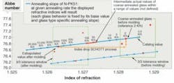
The annealing rate is not necessarily constant during the cooling process. Typical “average” annealing rates for precision molding are between 1000 K/h and 10,000 K/h (or higher). Because of the high annealing rate, the refractive index and Abbe number of N-PK51 is shifted to much lower values (see Fig. 2).
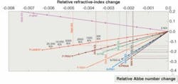
Process reproducibility enables predetermination of index drop based on initial refractive-index values and a set annealing rate. Attempting to predict a refractive-index drop based on the actual refractive-index values of the coarse-annealed glass would lead to errors due to undefined annealing conditions. Therefore, it is recommended to always use value projections based on a reference annealing rate of 2 K/h. The index drop differs between glass types because every glass has a different annealing slope (see Fig. 3).
Optical glasses for precision molding
Newly developed low-Tg glasses intended for use in precision molding include P-SK57, P-LASF47, P-PK53, and P-SF67. The letter “P” indicates that these glasses are produced for precision molding and are exclusively available as polished preform or precision gob. They are lead- and arsenic-free. “P-type” glasses, in general, are coarse annealed with tighter optical specifications (referred to as “P-quality”).
The N-type optical glasses can be used for precision molding because of their low transformation temperature. These glasses are also available in “P-quality” grade as polished preforms.
The refractive-index and Abbe-number data given in datasheets represent optical values of fine-annealed glasses. The cooling rate of a precision-molding process is much higher than common fine-annealing rates. Therefore, the refractive index of any precision-molded lens will be significantly lower than the catalogue values of the glass being used.
Optical glasses for precision molding are selected based on refractive index and Abbe number at a reference annealing rate of 2 K/h; tolerances for refractive index are ±0.0005 and for the Abbe number are ±0.5%. The refractive-index and Abbe-number tolerance steps for precision-molding glass are related to a reference annealing rate to achieve a reproducible process-dependent index drop.
Helge Vogt is New Products Manager at Schott Advanced Optics, Hattenbergstrasse 10, P.O. Box 2480, 55014 Mainz, Germany; e-mail: [email protected]; www.schott.com.


