RICK SEBASTIAN
Examination of a product catalog from any of the major optomechanical-hardware manufacturers reveals many optical mounts that cover a wide range of performance, functionality, and cost. Choosing the optimum mount for a specific application can seem daunting; however, the selection process is simplified once a few fundamental concepts are understood. A review of the basic functions that lens and mirror mounts must perform, as well as a comparison of how different mount designs accomplish these tasks, can assist the designer in selecting the proper mount for the job.
Defining an optical axis
The most common approach to building up an optical system is to establish an arbitrary fixed optical axis and then to add components one by one, aligning each in turn to this axis. When working on an optical table, for example, the axis is usually designed to reside at a set height above the table, and often runs parallel to the rows of mounting holes in the tabletop.
Optical elements that fold or offset the beam path, such as mirrors, prisms, and beamsplitters, are typically added and aligned first. When working with visible lasers, this alignment is often accomplished by steering the beam through one or more pinhole apertures that have been set mechanically to coincide with the desired optical axis. Crosshair targets can also be useful in performing this function.
Refractive components (for example, lenses) are inserted and aligned next. The exact method used for referencing this alignment varies depending upon the type of system under construction, the characteristics (such as focal length) of the components being used, and the level of precision required. Typical techniques for aligning lenses in laser systems include the use of pinhole apertures, monitoring the position of back reflections, or closely examining the shape of the focused spot.
In order to ease the construction of an optical system, it is necessary to have mounts that allow the components to be adjusted in various degrees of freedom with the required precision. Flat components (mirrors, beamsplitters, filters, and so on) usually only require θy and θz adjustment. (This article assumes that the x-axis is the optical axis, the y-axis is the horizontal axis, and the z-axis is the vertical axis.) For lenses, where misalignment causes angular deviation of the light beam, the necessary degrees of freedom generally include y- and z-axis adjustment. However, θyand θz motion and adjustment also are often required to avoid beam distortion due to a tilted lens.
Lens mounting
By their very nature, the post-mounted lens holders most commonly used in laboratory optical setups enable coarse adjustment in z and qz while constraining motion in y,θy, x and θx (see Fig. 1). In other words, the height at which the post is set can be varied and the post itself can be rotated. Adjustment in the y-axis often can be added easily by simply mounting the post holder in a base with slotted holes or on a translation stage. Including the capability for θy adjustment is not so straightforward, however, and adds cost and complexity to the mounting. Ideally, then, a post-mounted lens holder should retain the lens in such a way that its optical axis is automatically perpendicular to the axis of the post, to a high degree of precision. To see how this is best accomplished in practice, it is first necessary to understand the concept of centration.
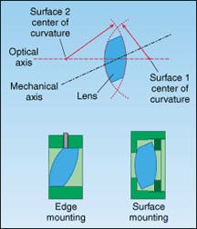
The optical axis of a conventional lens element with spherical surfaces is the line joining the center of curvature of each surface. For the commonly encountered plano-convex lens, the optical axis is a line that goes through the center of curvature of the radiused side and is perpendicular to the plano side. The mechanical axis is defined as the geometrical axis of the cylinder formed by the edge of the lens. Centration is a measure of the separation between the optical axis and the mechanical axis of the lens.
Centration errors can have an impact on certain lens-retaining schemes (see Fig. 2). When a lens is held by its edge, centration errors can leave the optical axis of the lens offset or tilted relative to the mount. In contrast, a mounting scheme that is referenced to the curved surface or surfaces of the lens avoids this problem. Mounting problems related to centration are most pronounced with short-focal-length lenses, because the effect of a given offset or tilt increases with decreasing focal length. Luckily, surface-mounting techniques are naturally more effective at accurately centering short-focal-length lenses due to their steep radii of curvature.Common lens holders
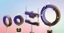
This knowledge about the required adjustment functionality and characteristics of typical mounting methods aids in reviewing various mount types. A few of the most commonly encountered types of mounts are discussed below (see Fig. 3).
A fixed lens holder using a single screw retainer demonstrates an extreme simplicity that yields its primary advantage—low cost. As just explained, however, edge-mounting can introduce component tilt, requiring the use of an additional mechanical component to provide offsetting adjustment. If needed, the cost of this additional hardware can negate any savings from the mount's lower price. Thus, this mount type is most useful for use with longer-focal-length lenses, or in lower-precision applications in which some wavefront distortion due to tilt can be tolerated.
A fixed lens holder using a retaining ring is a basic, workhorse optical mount that uses surface-mounting to provide adequate positioning accuracy for many optical setups. Its main disadvantage is a lack of flexibility; the mount is designed to hold lenses of a given diameter, so that each different lens diameter requires a unique holder.
Adding y-z adjustment to a retaining-ring lens holder yields a translating lens holder, which can achieve precise positioning, yet remains very compact. This type of mount provides adequate positioning functionality and resolution for the vast majority of applications. As before, it is limited to holding lenses of a single nominal diameter.
Adjustable lens holders come in several styles, depending upon manufacturer. The most common types are either a modified V-block that uses a vertically sliding clamp to retain the lens, or a configuration consisting of three radial screws—placed 120° apart—that are tightened to hold and position the lens. An adjustable lens holder can be used with a wide range of lens diameters, making it a useful accessory in the laboratory. Furthermore, this type of mount makes it easy to remove and replace a lens, if this is an experimental requirement. Since these mounts reference a point on the lens circumference, however, rather than the center of the lens, the height of the holder has to be readjusted for every different lens diameter used. Another drawback of adjustable lens holders is their use of edge-mounting.
A self-centering lens holder is essentially a three-jawed chuck that can retain lenses over a wide range of diameters, always locating the center of the lens at the same position. This is the most useful type of lens holder for applications in which different lenses must be quickly removed and replaced. The main disadvantages of this mount design are its high cost and the use of edge-mounting.
Mirror mounting
The performance and functionality requirements for mirror mounts are fundamentally different from those for lens holders. First, there is no need to adjust flat optics in the y-z plane; on the other hand, θy and θz motion is usually needed. In fact, for general-purpose mounts used to achieve a variety of beam-fold configurations, θy and θz travel ranges of up to 360° may be required.
While centration is not a consideration when mounting a flat optic, the method by which the optic is retained is important for another reason. Specifically, clamping with a single radial screw results in an asymmetric stress, which can distort the surface figure of the optic. This becomes a significant consideration when working with optics of λ/10 or better. In order to maintain surface figure for these high-quality optics, only mounts that employ a retaining ring or other symmetric clamping mechanism should be used.
The most important parameters that characterize mirror-mount performance are range, resolution, repeatability, and stability. Range refers to the total angular motion in each axis through which the mount can travel. Resolution is the smallest increment through which the mount can be reliably adjusted. Repeatability is the ability of the mount to return to a specific position for a given adjustment, while stability refers to how much the mount shifts over time due to various thermal and mechanical factors.
Utility and performance of mirror mounts is strongly influenced by their underlying design form. The three most popular designs are the kinematic, flexure, and gimbal mounts.
Kinematic mounts utilize the familiar "cone, groove, and flat" arrangement to enable tip and tilt adjustment over a limited range. The mirror is mounted on a movable plate, the angle of which is changed relative to a fixed plate by use of two adjustment screws at opposite corners. The plate is preloaded (pulled) against these screws and a fixed ball-bearing by a single coil spring.
Kinematic mounts are relatively simple to construct, and are typically the most economical of adjustable mounts. For this reason, they have become widely used. Their design inherently limits their range to around 5° to 10°. For several practical reasons, most kinematic mounts do not use very stiff springs; this, in turn, allows some play in the mount, limiting resolution and repeatability. It can also allow the mount to sag under heavy loads.
Another intrinsic problem with kinematic mounts is that their center of rotation is not at the surface of the mirror. This means that an angular adjustment also produces a translation in the reflected beam. Furthermore, since the tip and tilt adjustments are not truly orthogonal, the magnitude of this translation is not constant, but varies as the mount is adjusted. Together, beam translation and the lack of adjustment orthogonality may necessitate several adjustment iterations in order to align a system consisting of two or more kinematic mounts.
Flexure mounts utilize solid springs (typically leaf springs) to constrain the motion of the mirror-mounting plate, largely eliminating both twist and shear motion with respect to the back of the mount. Minimizing twist and shear improves both repeatability and stability. In addition, constraining shear enables this design to handle much heavier loads than a kinematic mount without sagging.
There are several different embodiments of the flexure mount design. In terms of performance, these versions range from units that have range, resolution, and cost similar to kinematic mounts, to products that deliver much higher resolution (a few arcseconds) with limited range. All flexure mount designs suffer from the same inherent limitation as kinematic mounts, however: specifically, they do not rotate about the front surface of the mirror, and the tip and tilt adjustments are therefore not truly orthogonal.
The axes of rotation for gimbal mounts are orthogonal, non-interacting, stationary, and centered on the optic. Moreover, a gimbal mount, if properly constructed, can deliver the ultimate in range, resolution, repeatability and stability. Such mounts are available in a wide variety of configurations. Usually, more economical gimbal mounts have limited angular range, while more sophisticated products have both high resolution and full 360° travel in both axes. The greater mechanical complexity of most gimbal mounts typically renders them more costly than kinematic or flexure mounts.
In general, optical mounts are often purchased as part of a system, rather than singly. As a result, it is useful to look beyond the performance of an individual piece of hardware. When purchasing optical mounts, the user should ensure that the mounts can interface with the dimensions of all the various types of optics in use (for example, diameters, thicknesses or shapes), and that the mechanical interface is flexible enough to enable a wide variety of configurations to be constructed.
Rick Sebastian is product manager of optomechanical hardware at Melles Griot, 16542 Millikan Avenue, Irvine, CA 92606; e-mail: [email protected].

