ANDREW MACGREGOR
Beam-intensity profiling is an essential tool in many aspects of photonics. The exact intensity distribution is critical in many applications—flow cytometry, laser printing, medical lasers, and cutting lasers are just a few examples. Beam-profile measurements can improve a product or process and lead to cost savings that more than pay for the profiler.
This brief tutorial describes the parameters that are measured, alternative measurement technologies, limitations, “added value” measurements such as profile fits and M-squared (M2), and how to specify your requirements. This tutorial does not address the measurement of high-power cutting lasers, wavefront phase, or lens modulation-transfer function.
Measure what?
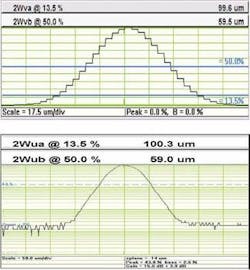
Typical laser-beam profiles include Gaussian; tophat (flat-top), either circular or rectangular; and line, with a Gaussian profile across the line and tophat along the line. The de facto industry-standard definition of beamwidth, which relates to a Gaussian beam shape, is the width at the 1/e2 intensity level (13.5% of the peak intensity). Additional requirements can include profile fits, focus position, divergence, pointing, and M2.
A Gaussian beam profile is the profile of a perfect TEM00 beam, the nominal output of a single-mode laser or fiber. What is the actual beam diameter and how close is it to a pure Gaussian?
A tophat profile is the typical output of an excimer laser, a multimode fiber, or the result of optical manipulation of a beam. What is the full width at half maximum (FWHM) of the beam? How flat is the top?
A line profile is generated using cylindrical optics. How uniform is the line width and the intensity along the line?
An array of spots can be generated using holographic optics. How uniform is the array spacing and the energy distribution?
A beam waist with a specific profile must be focused at a specific point (x,y,z) in space, requiring active alignment. How can this be achieved?
M2 is a delivery or acceptance specification on a laser. How is this measured?
Profiling techniques
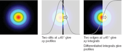
The three common profiling techniques are imaging, scanning slit, and scanning knife-edge (see Fig. 1). Images can be taken either by cameras using 2-D CCD or CMOS sensor arrays, or by (more expensive) raster scanners that measure the power transmitted through a scanned pinhole. Slit and knife-edge scanners translate a slit or knife-edge between the beam and a single element detector.
Slit and knife-edge approaches work well for beams close to Gaussian in profile and less well for more-structured beams. For small beams, such scanners provide a smooth profile without the pixel problems of cameras. They measure beam powers in the microwatt to watt regime (beam-diameter dependent) directly without intermediate attenuators, with specialist versions handling powers up to 100 W.
As the slit width approaches the beam diameter, better slit scanners compensate in the software for the profile-widening effect of the slit. With a 2.5 µm wide slit, this effect starts to matter below 25 µm; uncompensated, the effect produces a 15% error for a 5 µm beam diameter.
With knife-edge scanners, the integral of the intensity is differentiated to generate the beam profile, the sampling rate determining the effective resolution. Differentiating the signal increases high-frequency noise, so these scanners compromise high potential resolution against signal-to-noise ratio.
Which instrument?
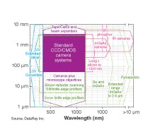
The “perfect” instrument that does everything does not exist. You will need to specify carefully and sometimes compromise (see Fig. 2). For accurate profiling, the total beam should lie within the sensor area. Power-handling capability is an additional consideration and can affect your decision. Slit/knife-edge scanners handle higher powers than cameras without additional attenuation. For beams less than 100 µm in width, a slit or knife-edge scanner will often give better results than a camera or a camera with microscope objective. With pulsed lasers, scanning slit/knife-edge systems construct the profile from the “comb” of individual pulses. See supplier specifications for the diameter-dependent minimum pulse-repetition rate supported by a given system. Adding optics such as beam expanders, tapers, and microscope objectives may introduce unacceptable levels of optical aberration.Cameras using microscope objectives to magnify the beam can handle smaller beams, but can introduce aberrations. Larger sensors, needed for directly imaging larger beams, are expensive. Beam expanders (and reducers) are long in the propagation direction and involve the near-field vs. far-field issues of Gaussian reimaging. Fiberoptic tapered cameras image up to 20 × 15 mm, but have up to ±3% of barrel or pincushion distortion. Cameras suitable for the IR may get expensive.
Additional considerations
Interfaces and analog-to-digital converters (ADCs). Here, the clear trend is toward compact port-powered USB 2.0 or Firewire-interfaced cameras. CMOS sensors with on-chip 10-bit ADCs are adequate for most applications. CCDs can have slightly lower noise, justifying 12-bit ADCs. Software algorithms can extend these ranges to see lower-intensity features in the wings.
Sensitivity and dynamic range. Cameras have a sensitivity problem—they are too sensitive. Typically, a filter (angled to avoid fringing) with a neutral density (ND) of 4 is required simply to block the room lights. Both the camera and ND filter are wavelength-dependent. Look for curves showing the range of powers or pulse energies handled vs. beam diameter and wavelength. Add-on sampling or attenuation can increase power handling. Good systems offer auto-exposure on continuous-wave (CW) beams with greater than a 10,000:1 range (greater than 40 dB dynamic-exposure range). Look for true continuous auto-exposure, not pulldown-menu stepped exposure, which uses amplifier gain to fill in the steps. Additional sampling or attenuation, whether built-in or added on, can increase dynamic range. For pulsed-beam single-pulse capture, auto-exposure will not help you, but sensor amplifier gain and/or variable attenuators can.
CW or pulsed beams. All cameras will work fine on CW beams. But scrolling shutters will not work on most pulsed beams—you need synchronous shutter capability. Most cameras offer a synchronization input for pulsed lasers, and auto-capture of single pulses from a pulse train. For pulsed beams, look for the minimum exposure time. For example, a 40 µs minimum shutter will capture single pulses from a 25 kHz pulse train, but will not capture every pulse in the pulse train. The number of pulses captured per second will depend on the camera and the capture area.
Specs matter
As a supplier, we frequently receive an inquiry from prospective customers for one instrument to meet every conceivable measurement requirement. A better approach is to help us determine your needs. Before talking to a supplier, clarify and distinguish your “essential” and “desirable” measurement requirements. Identify beam dimensions and accuracy requirements, wavelength(s), powers for CW, and pulse energies for pulsed—and, if pulsed, the pulse characteristics. What might be special about your requirement? Your interest is in getting the best fit to your requirements. The supplier’s interest is in selling you an instrument that you love because it meets your requirements.
Great software does what you require and is bug-free. Most suppliers offer sample software and data for your evaluation. All software is not created equal. There are differences in the display approaches and in functionality. Do you need basic functions or sophisticated fits? Do you need logarithmic profile display, data logging, measurement statistics, beam-wander information, Active-X or LabVIEW (National Instruments; Austin, TX) software interfacing for automated alignment, and so on? If you need additional functions, does your supplier write its own software and can they be added? Again, carefully define what you need.
Added-value measurements
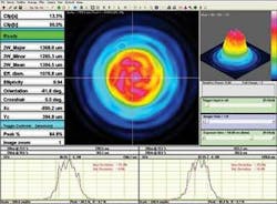
Sometimes you will need more than simply x-y beam profiles and dimensions (see Fig. 4). Common added measurements are a least-squares Gaussian fit or the ability to determine the flatness of tophat beams. Divergence, collimation, or focus position of a beam can be determined by moving a single plane profiler in z, but this is not a real-time measurement and limits manual or automatic adjustment of a beam. Multiplane real-time profilers offer major time and cost savings in such applications.For determining the angular output distribution of a source, x-y profilers and imagers can handle low-numerical-aperture beams. High-angle beams and full polar distribution require specialized goniometric scanners.
M2 characterizes the degree of imperfection of a real-world laser beam. An M2 of 1 is diffraction-limited TEM00 perfection. Most beams are not perfect—a laboratory HeNe laser has an M2 of around 1.05 to 1.2. The closer M2 is to 1, the more tightly the beam can be focused. M2 is the ratio of the far-field divergence of the actual beam to that of a TEM00 beam with the same waist diameter. The beam diameter varies hyperbolically with distance z from the beam waist. ISO 11146 defines exact requirements for M2 measurement in terms of beam-waist diameter and far-field divergence. See supplier websites for more detailed information.
There are several excellent, cost-effective beam-profiling instruments out there—and some so-so ones. All have a “sweet” range in their specs and limitations at the lowest nominal beam diameters. No supplier has a monopoly of excellence across the whole range of instruments and applications. You will spend anywhere between about $3,500 to more than $10,000 for your beam profiler. Be clear about what you need to measure and you should be quite satisfied.
Andrew MacGregor is vice president of operations and support at DataRay Inc., 605 Stapp Rd., Boulder Creek, CA 95006; e-mail: [email protected]; www.dataray.com


