Optical measurement techniques that are based on the interference of coherent light have been used in both research and industrial settings for many decades. Originally based on narrow-line discharge lamps, interferometric techniques have been used with increasing frequency in recent years because of the availability of economical laser sources with superior spatial and spectral coherence properties. Today, laser-based interferometers are routinely used for quality-control applications throughout the optics-manufacturing industry, while research-grade instruments are used for an extensive range of precision measurements.
In a typical manufacturing application, the optical quality of a finished product is determined by placing it inside a laser-excited interferometer. Phase aberrations produced by optical inhomogeneities are indicated by distortions of the normally periodic interference pattern. Advanced computer algorithms are used to interpret the fringe pattern, ultimately yielding a qualitative map of the phase errors across the sample aperture.
In addition to component characterization, interferometers can be used to determine the output wavelength, modal spectrum, and collimation properties of a laser source. These measurements are typically accomplished by focusing the laser output into the interferometer and observing the transmitted light.
Interferometers in which a single, polished (and sometimes coated) plate is used to produce an interference pattern are simple in both construction and operation. The Fizeau wavelength analyzer manufactured by New Focus (Santa Clara, CA) is a good example of this kind of device. Consisting of a single, uncoated plate, an entrance aperture, and a charge-coupled-device array, this instrument has a wavelength accuracy of 0.01 nm and a maximum resolution of 0.001 nm. Other fixed-plate beam analyzers include shearing interferometers that provide information on wavefront curvature and Fabry-Perot etalons used for the verification of single-frequency operation.
In those cases in which a more accurate determination of longitudinal-mode spectrum is required, scanning-mirror devices are typically used. Invented shortly after the laser, these instruments can quickly provide information on the longitudinal-mode spectrum and/or line width of a laser. Subsequent sections of this article look at the theory and operation of these devices.
Transmission resonance measures modal spectrum
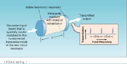
Interferometric analysis of the longitudinal-mode spectrum of an operating laser is based on the well-known theory of transmission through a spherical mirror resonator.1,2 In an idealized system, the output of a single-frequency laser is perfectly mode-matched to the fundamental TEM00 transverse mode of a stable, two-mirror cavity (see Fig. 1). The cavity transmission function is sharply peaked at frequencies determined by the cavity length and index of the intracavity medium. According to basic resonator theory, resonant enhancement of the intracavity field and cavity transmission occur when the mirror spacing is equal to an integral number of half-wavelengths (standing-wave condition). Mathematically, this condition is met when the input frequency is an integral multiple of the free spectral range, c/2nL, where c is the velocity of light, n is the index of refraction of the intracavity medium, and L is the spacing of the mirrors.To determine the longitudinal-mode spectrum of a laser using a setup similar to that of Fig. 1, the transmitted power is measured as the cavity length is scanned. If the frequency spread of the input spectrum is smaller than the free spectral range of the cavity, the plot of intensity versus cavity length provides an accurate description of the longitudinal-mode spectrum. Typically, a piezoelectric translator is used to repetitively scan the cavity length, and the transmitted power is displayed on an oscilloscope that is synchronized to the piezo drive.
Confocal cavities ease mode-matching
While any stable resonator can be used to analyze the modal spectrum of an unknown source, the ease with which an unambiguous measurement can be made is strongly dependent on the cavity design. As stated in the preceding section, a scanning interferometer with a free spectral range that is greater than the output-frequency spread of the source is needed to accurately determine the modal spectrum. In addition, it is highly desirable to maximize the resolution and ease of alignment. From a design standpoint, these performance issues are coupled because the length of the resonator has an effect on each of them. In addition, the resolution is determined by mirror losses, and the transverse-mode spectrum is ultimately determined by the mirror curvature.
For most resonator designs, accurate mode-matching of the input beam to the fundamental transverse mode is required because higher-order transverse modes have resonant frequencies that are different from those for the fundamental. Thus, a single-frequency source that is poorly mode-matched to the resonator will produce a transmission function that is qualitatively similar to that observed with a multimode (multifrequency) input. While easily described on paper, this condition is much harder to achieve in practice.
Theoretically, the resonant frequency of an arbitrary spatial mode with "l" nulls in the horizontal direction and "m" in the vertical (TEMlmmode) is related to mirror curvature and spacing2
[1]
where the negative sign is used when the absolute value of each of the bracketed quantities under the radical is negative, and the positive sign is chosen in the other case. (Note: the bracketed terms have the same sign if the resonator is stable.)
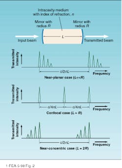
The modal spectrum predicted by this equation is determined by the cavity design (see Fig. 2). Near the cavity-stability limits (near-planar and near-concentric cavities), frequencies of higher-order transverse modes are spaced at equal distances on the high- and low-frequency side of the fundamental. If such a cavity is used to analyze the output of a single-frequency laser and the beam is not spatially mode-matched to the TEM00 mode, transmission peaks will be observed at several different frequencies due to the excitation of other transverse modes.In case of the confocal design in which two identical concave mirrors are separated by a distance equal to their common radius of curvature, the longitudinal-mode spectrum is simplified considerably. Substitution of the confocal length condition (L = R) in Eq. 1 yields the following, simplified expression
[2]
From this equation we see that the frequencies of higher-order transverse modes are coincident with those of the fundamental in cases in which the sum of "l" and "m" is odd and separated from them by c/4nL when it is even. When used for modal analysis, the confocal design eliminates the requirement for spatial mode-matching because the excitation of higher-order modes does not give rise to new resonant frequencies. Unfortunately, this advantage is not without cost, because the existence of an intermediate set of modal frequencies reduces the free spectral range of the confocal cavity by a factor of two (c/4nL as opposed to c/2nL in the nonconfocal case).
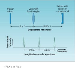
Theoretically, there are a number of resonator designs with a simplified modal spectrum.3 Characterized by a specific form of the ABCD ray matrix corresponding to a single cavity roundtrip, a half-degenerate resonator has a modal spectrum identical to the confocal case—higher-order modes that are spaced at multiples of c/4nL. In addition, fully degenerate cavities similar to the one in Fig. 3 have higher-order modal frequencies that are exactly matched to those of the fundamental. As a result, the full power of an input beam with arbitrary transverse profile is matched into the cavity at the resonant frequency. While superior to the confocal design with respect to mode-matching properties, degenerate designs are rarely used in practice due to complexities of construction and alignment.Good coatings yield high resolution
In addition to providing information on the longitudinal-mode spectrum of a laser source, a scanning interferometer also can provide information on the frequency stability of a single-frequency source. In theory, the frequency resolution of an interferometer is determined by the mirror reflectivities, cavity length, and nontransmission losses. In practice, it is also related to the mechanical stability of the interferometer cavity.
Neglecting mechanical effects, sharply defined transmission peaks are achieved by minimizing the nontransmission losses of the resonator mirrors. The ‘finesse’ of the etalon, defined as the ratio of free spectral range to peak width, provides a quantitative basis for the evaluation of instrument performance.
In the scanning confocal instrument manufactured by Burleigh Instruments (Fishers Park, NY), the 37.5-mm cavity length corresponds to a free spectral range of 2 GHz. Careful fabrication of the comparatively short-radius mirrors yields a finesse of 300, corresponding to a resolution of approximately 6.7 MHz.
By using very short cavity lengths and ultralow-loss mirrors, Newport Corp. (Irvine, CA) has developed a product line with significantly larger values of free spectral range and finesse (FSR of 7500 GHz and finesse of 10,000, for example). Unfortunately, this specification could only be accomplished by giving up the alignment advantages of the confocal design.
Backreflections eliminated
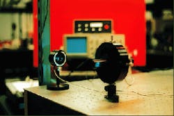
Commercial interferometric optical spectrum analyzers typically consist of a piezoelectrically scanned cavity, detector, and custom electronics module. Careful attention to the mechanical design of the cavity has resulted in structures that are comparatively immune to vibration and, in the case confocal instruments, can be easily tuned to the correct cavity length. Silicon detectors provide wavelength coverage from the deep-blue to near-infrared (near-IR) regions, while germanium is typically used for longer wavelengths. The electronics module is designed to perform the multiple functions of scanning the cavity length, amplifying the detector signal, and providing the outputs needed to synchronize an oscilloscope trace to the piezo scan. Front-panel controls allow the scan rate, range, and midpoint to be adjusted in addition to the gain of the amplifier. One or more cables are used to connect the electronics module to the interferometer (see photo at top of this page).
To analyze the output of a laser using a confocal instrument, the cavity length must first be set to the correct value. This setting is typically accomplished by looking at the cavity throughput while adjusting the cavity length. Once the cavity length has been set, the input-beam alignment is optimized to yield the maximum throughput.
In many cases, the proper alignment of the laser to the confocal cavity produces backreflections that can destabilize the laser. Attenuation of the input beam using an angle reflector or neutral-density filter usually eliminates this problem because the intensity of the backreflected radiation is reduced by the square of the input attenuation. In cases where this solution is inadequate, Faraday isolators or other more elaborate schemes may be used.
As evident from the discussion above, the selection and correct usage of a scanning mirror optical spectrum analyzer requires a good understanding of its basic operation. Given the range of commercial options, a potential user should first determine the free spectral range and resolution required for his or her application. After devices satisfying these criteria are identified, ease of use and cost variables should be considered along with the projected lifetime and alternative uses of the instrument.
Regardless of the specific features chosen, the scanning cavity optical spectrum analyzer promises to remain one of the simplest and most accurate methods for laser mode analysis. Hopefully, continued advances in coating technology and optomechanical design will lead to improved devices that combine the alignment advantages of the confocal design with the large values of finesse that have been achieved with nondegenerate cavities.
REFERENCES
1. R. L. Fork, D. R. Herriott, and H. Kogelnik, Appl. Opt. 3, 1471 (1964).
2. A. E. Siegman, Lasers, University Science Books, Mill Valley, CA, 1986, p. 744.
3. J. A. Arnaud, Appl. Opt. 8, 189 (1969).


