From wind-turbine blades to large vehicle frames, offshore oil rigs, boat hulls, and prefabricated bridges, many applications exist where engineers need to accurately measure deflections and twists in large structures. For many of these situations, however, it is not practical to use traditional methods, such as accelerometers or other ground-referenced techniques.
Now, a modular laser-based tool from Boxboro Systems (Boxborough, MA), called the DTMS (deflection and twist measurement system), enables these deformations to be measured in real time, at high spatial resolution, and over large displacement ranges.
The basic DTMS module incorporates a red laser-diode crosshair projector and a detector unit. The detector section consists of four linear photodiode arrays arranged in a square pattern. One of these modules (the root module) is rigidly mounted at one end of the structure to be tested, with the laser beams pointing towards the other end. A second module (the end module) is mounted on the other end of the test structure in a direct line of sight to the first.
In operation, both modules sense the position of the crosshair illumination pattern from the other module, based on where it intersects the four photodiode arrays. In this way, the system, aided by its computer, simultaneously measures five axes of motion at the end module, including deflection, twist, and lateral displacement, all relative to the root module.
Relay concept
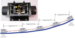
One essential new development for this system is the relay concept (see figure). Here, measurements along greater distances are divided into a series of fixed segments using a series of identical modules. These double-ended modules are mounted at user-selected points along the structure to be tested. Each of these bidirectional relay modules is completely symmetric; the compact relay unit incorporates two identical laser-diode projector and detector array assemblies, positioned 180° to each other. A simpler version is also available with unidirectional modules, which allows motion in just three degrees of freedom to be measured.
The laser diode projectors use refractive optics rather than holographic optic elements (HOEs). The reason is that a far-field crosshair produced by HOEs is really an interference pattern and can have intensity irregularities that vary with distance as well as with any drifts in laser-diode wavelength, which could compromise the measurements in this system.
The DTMS uses vector-based algorithms, where the position of each relay unit is computed as a vector relative to the adjacent unit, and ultimately to one of the end units. For each relay module, the origin of the coordinate system is halfway between the two ends of the enclosure and 66.5 mm up from the bottom of the base. In the simplest format, the laser-diode projectors are held in fixed mounts inside the relay modules. But in many instances, especially those involving highly curved and/or flexed parts, better measurements with fewer segments can be obtained by providing the ability to tilt the beam in two directions (θx and θy) relative to the module baseplate. This is enabled by holding the laser-diode projector in an adjustable mount.
Finding the right mount
For vector-based metrology, accuracy is maximized by mounting the laser in a goniometric manner, so that beam angular adjustment does not also produce beam translation (walk-off of the beam). But traditional goniometers would increase the size of the otherwise compact modules, raise their cost, and also limit easy access to at least one of the two adjustment screws. Instead, the system uses patented mounts (model IAG100P) from Siskiyou Corporation (Grants Pass, OR) that have the compact size of kinematic mounts but deliver goniometric motion (rotation about the optical center). Just as important, both the 100 threads-per-inch (tpi) adjustment screws are top mounted above the beam path, making them easily accessible. The mounts (which were designed by Siskiyou for positioning of polarizing optics but found by Boxboro Systems to be suitable for its DTMS) incorporate a rigid locking mechanism that is top surface mounted and include a lockable dial to enable rotation of the crosshair around the z axis for optimization of DTMS precision.
The resolution of the system is set by the 0.064 mm pixel pitch of the detector arrays, and the range of deflection is determined by the single-segment range multiplied by the square of the number of segments, where the single-segment range is the length of the detector arrays (in this case, 23.5 mm).
Dan Handman, president of Boxboro Systems, says the DTMS is an ideal solution for measurements of highly curved parts and/or for large deflections. Moreover, the ability to simultaneously measure movements at multiple points in real time (100 Hz sampling rate) enables the mode shape of multiple resonant motions and overtones to be ascertained, including their relative phase.

