When manufacturers are considering which optical components to use in their system, common specifications that are considered include magnification, numerical aperture (NA), focal length, and working distance. However, there are other critical factors to consider that can have a major impact on the overall quality of the final product. Here, we explore three of these factors—wavefront aberration control, a compensation-free design, and improvements provided by novel lens manufacturing technology.
The importance of wavefront aberration control
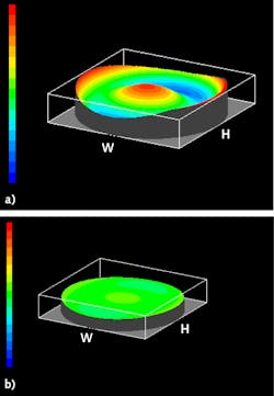
Wavefront aberrations are the difference between an ideal wavefront used to form an ideal microscope image and the actual wavefront. The degree of wavefront aberration contributes to defects in the visual image. The Strehl ratio, point spread function, and modular transfer function are three additional ways to assess an objective’s performance.
The standard way an objective’s optical performance is measured is the Strehl ratio. This is the ratio, expressed as a percentage, of the convergence ratio attainable in an actual optical system with aberrations to the convergence ratio (or the intensity at the center) in the image field of an ideal aplanatic optical system. This means the higher the Strehl ratio, the higher the optical system’s quality. Objectives with a Strehl ratio of 95% or higher are considered at the peak optical performance.
The point spread function (PSF) is used to know the actual resolution, while the modular transfer function (MTF) describes the percent modulation or change in contrast that occurs between the input and output signals for signal-handing delivery (microscope optics).2 MTF can be plotted versus spatial frequency, focus position, or field number.
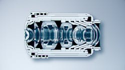
Performance improvements in microscope objectives have led to a more complex and miniaturized internal lens structure (see Fig. 1). As a result, objectives tend to have differences in quality due to manufacturing errors, and sometimes these differences cause variations in a final product’s performance.
To minimize the chance of these kinds of variations, technicians must measure the wavefront aberration during the assembly processes for certain high-performance objectives (see Fig. 2).Integrating objectives with wavefront aberration control
Here are the top three reasons to integrate objective lenses with wavefront aberration control into your microscope design:
1. Produces stable, high-quality images. The image quality affects how quickly and accurately a device’s software can measure it. Objectives with wavefront aberration control can provide stable and high image quality, so if reliability matters in your final product, integrating an objective with wavefront aberration control is a must.
2. Reduces costs. An imaging device that fails to work properly due to objective performance variations will incur extra costs. For instance, you may need to discard the objective and buy a replacement. Objectives with wavefront aberration control can reduce these costs due to their high performance.
3. Stabilizes your product delivery schedule. A device that’s expected to deliver high performance will need extra adjustments to cope with objective performance variations. This can mean a longer production lead time. In contrast, adopting objectives designed with wavefront aberration control for consistent quality means you can deliver devices on promised delivery dates. In addition, you can keep a backup inventory of dependable objectives.
While wavefront aberration control is important for the reasons discussed above, it is not the only key design aspect in high-end objective lens assemblies. To ensure high image quality and design/commercial flexibility—especially for system manufacturers—compensation-free optics are important.
Compensation-free optics and their advantages
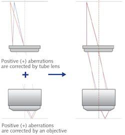
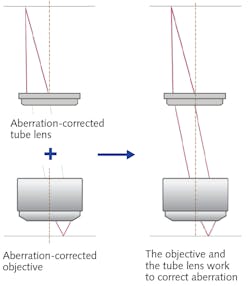
Infinity-corrected imaging systems in microscopy typically consist of an objective and a tube lens, in its simplest form. The objective is placed close to the object of interest, and the tube lens focuses the collected light from the objective to the camera sensor or ocular. To produce the highest quality images, aberration correction is emphasized, and this is generally accomplished in one of two ways: the compensation method and the compensation-free method.There are a few advantages to the compensation-free method. For laser-based illumination systems for fluorescence or monochromatic imaging, the laser is introduced into the optical path between the tube lens and objective, then focused by the objective to the sample. Since the tube lens does not affect laser focus in this case, the compensation-free design helps ensure optimal focus, the tightest possible spot size, and chromatic correction independent of the laser wavelength (within reason).
Another benefit is the acquisition of clear images with little to no color blurring across the field of view, even if the objective is used independently of a tube lens. This is especially important because field numbers and camera sensors continue to increase in size. For example, both X Line objectives and the super wide tube lens (SWTLU-C) are corrected for aberrations within a range of 400 to 1000 nm. Together, they offer a solution for imaging systems where the objective and tube lens are required over a large 26.5 mm field. And because they’re compensation-free, both the objectives and tube lens could be used independently while still offering strong chromatic correction over the broad spectral range described above.
For manufacturing teams and system designers, the compensation-free method can be used to maintain consistent, uniform image quality and chromatic correction across super-wide FOVs, even if used with commercial stock lenses from third-party suppliers.
Improving objective quality
Researchers use microscopes and imaging devices as essential tools for advancing their science, and objective lenses are crucial components of the system. Many applications benefit from high-quality images with a large field of view (FOV), but there is usually a tradeoff where improvements in one area of imaging, such as flatness, lead to a decrease in another area.
Ongoing innovation in manufacturing technologies means researchers can enhance their work with newer high-performance objectives that offer improved optical performance in three critical areas—a larger NA, better image flatness, and a wider range of chromatic correction. These advances enable high-quality, large FOV imaging for versatility in numerous applications.
Conventional objective lens manufacturing technology forced a tradeoff between NA, image flatness, and chromatic correction, making it difficult to improve all three in one objective. In the past, engineers concentrated on designing objectives that were exceptional in one of these three critical areas so that users could choose the objective that best suited their application.
These objectives were engineered to acquire high-resolution images in a relatively narrow area (smaller FOV). Sometimes, these images were problematic when using image analysis software since the processing algorithms normally assume that the images have no optical aberration or peripheral darkening. It is difficult to obtain reliable, accurate processing data unless the objectives deliver high-resolution, high-quality images over a large FOV.
Newer manufacturing technology used to make more advanced objectives solves these challenges. Some companies, including Olympus, aim to play a role in better enabling the life science, industrial, and medical research and diagnostic fields by providing image analysis and microscope-based imaging system manufacturers with the latest high-performance objectives to integrate into their devices.
Our conversations with manufacturers often reveal that they have difficulty ensuring that their devices provide uniform-quality images. Even manufacturers that design high-performance devices will fail to achieve the quality, cost, and lead time they promised if significant variations or errors occur in their manufacturing processes due to the performance of integrated microscope objectives.
The newest imaging breakthrough objectives—X Line objectives—break traditional imaging barriers by delivering high levels of NA, chromatic aberration correction, and flatness at the same time—three critical parameters traded off against each other in the past.1 Another advance they adopt is wavefront aberration control, offering optical engineers and system designers a solution to problems stemming from variations in objective performance.Objective lenses and tube lenses are typically defined by magnification, NA, focal length, and working distance. These data points are typically sufficient when using an objective on a manufacturer’s standard frame. However, there is more beyond the published specifications for designers and system manufacturers. The lens’s correction, flatness, aberrations, design spectrum, and compensation method described above are some of the lesser known, but still necessary and important to understand features to optimize your system to achieve maximum performance.
ACKNOWLEDGMENT
X Line is a trademark of Olympus Corporation.
REFERENCES
1. See https://bit.ly/XLineObjectives.
2. D. B. Murphy, Fundamentals of Light Microscopy and Electronic Imaging, 252 (2001).


