YUJI IWAI
As Geiger-mode avalanche photodiodes (APDs) have become more popular and different players have entered the market, it’s become increasingly difficult to navigate the different implementations of the technology. Although APDs all operate on the same basic principle, the similarities end there. One simple way to categorize the different Geiger-mode APDs is by the number of micropixels they contain.
The single pixel implementation is popularly called the SPAD (single-photon avalanche diode). It can easily be thermoelectrically cooled due to its small size (~100 µm), resulting in very low dark counts. Low dark counts are crucial for the SPAD since it can only count single-photon events. The speed with which the SPAD can count photons depends on its reset time (or “dead time”). Extensive research has been done on active quenching circuits to shorten the reset time and broaden the dynamic range.1
The other type of Geiger-mode APDs are multipixel implementations (multiple micropixels all tied together to a common cathode and anode)—commonly known as silicon photomultipliers (SiPMs) because they are capable of counting multiphoton events, similar to traditional photomultipliers (PMTs). In this implementation, it is possible to trigger on these multiphoton events and use them for timing measurements.
When the multipixel implementation first appeared on the market, much effort was devoted to characterizing the device. Compared with the decades of experience that researchers have accumulated looking at the physics and application of PMTs, there was a lot of catching up to do. Would the newer, solid-state technology be able to overcome the shortfalls of the more mature vacuum technology? There was, and still is, a lot of hype about the multiphoton pixel counter (MPPC) SiPM. As an applications engineer at Hamamatsu, one of my key responsibilities is to manage expectations. Some users expect capabilities far beyond those of any detector, while others are disheartened by the fact that the MPPC doesn’t behave like the PMT they’ve used for decades. The reality is that the MPPC is far from being a drop-in substitute for a PMT. Just like any other type of detector, it has its own unique characteristics.
Modeling and simulation of the MPPC
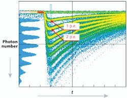
One of the unique characteristics of the MPPC is the shape of the single-photon pulse signal. Unlike the PMT, which has a somewhat Gaussian pulse shape, the MPPC exhibits a relatively long pulse decay time (tf) compared with its relatively short rise time (tr). This is usually the first thing that users notice when they look at the MPPC pulse with an oscilloscope. Since the initial major applications for the MPPC were high-energy physics and medical imaging, timing resolution was a key parameter of major concern. It continues to be an area of study, with the goal of producing a pulse with a short tr and high pulse height (see Fig. 1).
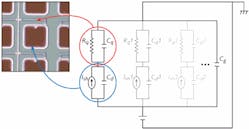
Initial results for single-photon timing resolution were very promising, with 220 ps FWHM being reported on the datasheet first released for the MPPC.2 However, after modeling and simulating the behaviors of the MPPC, a couple of parameters were identified that can be fine-tuned to improve upon the initial results (see Fig. 2).3–5Manufacturing experience
Any time there are variations within a MPPC, its performance suffers. Initial efforts to improve timing resolution were centered on controlling this variability. The first step taken was to see the actual effects of tuning the quenching capacitance and pixel capacitance by shrinking the micropixel size while keeping the same micropixel pitch. This alone lowered the Cd and increased the Cq. It was found that the Cq could be increased even further by widening the traces inside the MPPC. The actual effects of these two changes can readily be seen on an oscilloscope. The peak amplitude increased, the decay time decreased, and the pulse shape uniformity was improved.
As refinements were made to the overall process, other improvements were observed. Dark counts for the 50-µm-pitch, 3 × 3 mm MPPC have been observed to decrease by an average factor of two. Such improvements allow the MPPC to be used easily at room temperature without cooling.
Arrays
Applications such as positron emission tomography (PET) that require large-area imagers are driving interest in larger arrays. Even a small 2 × 2-channel array would significantly reduce the complexity of the optics and electronics needed in a PET scanner. While the nonmagnetic properties of the MPPC are already appealing for PET applications, the ability to work with preconstructed arrays makes working with these devices much easier. There are two different approaches that can create a large-area array of MPPCs: lining up discrete elements or designing a monolithic array.
Fabricating an array by combining discrete MPPCs is a relatively easy task. To ensure overall uniform gain, the voltages applied to each discrete MPPC must either be individually adjusted or the MPPCs must be presorted based on performance. Since one can select and sort discrete MPPCs from multiple lots, it is possible to fabricate an array that is more uniform in gain than would otherwise be possible if all the devices were from the same wafer.
Monolithic arrays are much more risky from a yield perspective. If the variation in breakdown voltage is large enough, some channels may not operate in Geiger-mode. The other extreme would be if the overvoltage value is too high for a channel. Even if the difference between channels was not that significant, the uniformity would undoubtedly get more problematic as the array size increases. Although it is possible to have a monolithic MPPC array that is the size of the silicon wafer on which it is made, the detector would be subject to the same gain nonuniformity across the wafer.
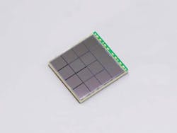
Another challenge behind making a monolithic array is the design of the trace layout. The impedance of the aluminum traces significantly affects the pulse shape so any variation in the length or width of these traces would change the pulse shape coming out of each MPPC channel in the array. In the case of a 4 × 4-channel monolithic MPPC array, the traces are routed so that the aluminum trace lengths are all equalized to the longest path a channel would need to take (see Fig. 3).Electronics
Since the gain of MPPCs is sensitive to temperature fluctuations, a mechanism is needed to maintain constant output. As in silicon APDs, the breakdown voltage shifts up at higher temperatures. For the MPPC, the temperature coefficient is about 56 mV/°C. There are various temperature compensation methods to deal with this problem. Most common is adjustment of the overvoltage according to the temperature, or a thermoelectric cooler can be used to keep the temperature constant, although doing this on a large scale quickly becomes a complicated task due to the number of MPPCs.
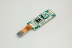
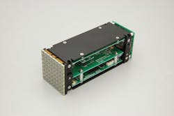
The same complexity exists for any readout electronics that may be implemented—the more signals to be processed, the more components are required. In many applications, real estate becomes the limiting factor so there has been much interest in mixed-signal low-noise ICs to handle signal amplification and processing for arrays of MPPCs.A general application 16-channel signal application-specific integrated circuit (ASIC) is currently available in modules using discrete and monolithic arrays. The requirements for such an ASIC were low input impedance, high output impedance, bandwidth greater than 100 MHz, and clamp circuitry to reject noise. This particular ASIC is based on current mirror circuits. Even though process improvements have minimized gain differences between channels in monolithic arrays, a separate 32-channel digital-to-analog converter (DAC) ASIC was developed that can offset any gain nonuniformities in the MPPC array (see Fig. 4).
The resistive readout scheme has been popular in the medical imaging community for reading out large arrays of PMTs. This same readout scheme has been implemented in the discrete 64-channel MPPC array, which provides four position-encoded analog outputs (see Fig. 5).The MPPC has quickly changed from being a novel yet unproven technology to a well understood and trusted technology. There are still many more unexplored applications, however. This is truly an exciting time for the MPPC.
REFERENCES
1. S. Cova, et al., “Active-Quenching and Gating Circuits for Single-Photon Avalanche Diodes (SPADs),” IEEE Trans. on Nucl. Sci., NS-29, 599–601 (1982).
2. Multi-Pixel Photon Counter catalog from Hamamatsu Photonics K.K.
3. F. Corsi et al., “Modelling a silicon photomultiplier (SiPM) as a signal source for optimum front-end Design,” NIM, A572 (2007).
4. K.A. Wangerin et al., “Passive Electrical Model of Silicon Photomultipliers,” IEEE Nucl. Sci. Symp. (2008).
5. C.L. Kim, “Method to improve SSPM Timing Resolution: Pulse Shape,” Proc. Sci. (PoS), Intl. Workshop on New Photon Detectors, PD09-010 (2009).
6. H. Otono et al., “Study of the internal mechanisms of Pixelized Photon Detectors operated in Geiger-mode,” arXiv:0808.2541v1 (Aug. 19, 2008).
7. “Characteristics and Use of Si APD,” technote from Hamamatsu Photonics K.K.
8. K. Yamamura et al., “Production and Development status of MPPC,” Proc. Sci. (PoS), Intl. Workshop on New Photon Detectors, PD09-017 (2009).
9. K. Yamamato et al., “Newly developed semiconductor detectors by Hamamatsu,” Proc. Sci. (PoS), Intl. Workshop on New Photon Detectors, PD07-004 (2007).
Yuji Iwai is an applications engineer at Hamamatsu Corp., Bridgewater, NJ 08807; e-mail: [email protected]; http://sales.hamamatsu.com.
