A new generation of fiber lasers operating in the near-infrared (NIR) at 1070nm has unique properties such as high pulse energy with high peak power, high average power, and very good beam quality. Consequently, extreme high-power densities are possible, allowing for adequate coupling and high-quality machining of materials that are typically transparent at these wavelengths. These lasers, known as quasi-continuous-wave (QCW) ytterbium fiber lasers, can operate with variable pulse length in pulsed mode at high peak power and high repetition rate, as well as in continuous-wave (CW) mode at high average power. This translates into high-throughput machining, from drilling to scribing and cutting.
QCW fiber lasers can be either single- or multi-transverse mode, which allows adjustment of the focused beam size as needed for the process. The beam quality of a single-mode fiber (14μm diameter) is very fine, with an M2 <1.05. Since the beam can be tightly focused nearly to its diffraction limit, spot sizes below 20μm in diameter are possible, allowing for fine structuring and achieving high power densities above 107W/cm2. This is typically enough to induce coupling and localized melting on most materials-even those that have poor linear absorption at this NIR wavelength, such as "white ceramics" and sapphire.
Alumina (polycrystalline Al203) and aluminum nitride (AlN) are considered high-performance, thermal-conducting substrates and are used in a large number of industries, such as for light-emitting diodes (LEDs), radio frequency (RF), and microwave packaging. High-speed hole drilling and singulation of these materials is very important to keep manufacturing costs low. On the other hand, monocrystalline Al2O3, also known as sapphire, has outstanding characteristics such as high hardness-second only to diamond. Compared to typical optical glass, sapphire is much stronger and more scratch-resistant, has a wide optical transmission ranging from ultraviolet (UV) to NIR, and has a high thermal conductivity. Sapphire is widely used in the LED industry as a substrate to grow light-emitting epitaxial layers by metal-organic chemical vapor deposition (MOCVD). Its use has increased dramatically in the last few years due to the fast expansion of LEDs for back-lighting on displays and, more recently, general lighting. In addition, sapphire has recently expanded to the consumer electronics markets, where it is being used in mobile phones as the camera lens cover, the home button, or the entire display.
QCW fiber laser and processing techniques
QCW fiber lasers cover a wide range of average and peak powers, with some models allowing in excess of 1 and 10kW, respectively. These are compact lasers, with high wall plug efficiency above 30%, maintenance-free operation, and reduced cost of ownership. One of the QCW fiber lasers used here (YLM-150-1500-QCW) has a single-mode core fiber (14μm), allowing for a maximum peak power of 1.5kW and average power of 150W (up to 250W in CW mode only). A YLR-300-3000-QCW laser also was used with a multimode fiber (50μm), allowing for a maximum peak power of 3kW and average power of 300W. The lasers operate in pulsed mode and also in CW mode. Pulse duration for both lasers is adjustable between 10μs and 50 ms, with exact range depending on laser model and parameters used.
With these relatively long-duration pulses, a thermal machining process is often used, where the material temperature is locally raised above its melting point and an assist-process gas (e.g., air, N2, oxygen, or argon) is used to mechanically expel the molten material. On a typical workstation setup, the beam/fiber enters a collimator with a focal length typically in the range of 50 to 150mm. The fiber output is collimated and guided into a cutting head, where it is imaged/focused by an objective lens, resulting in an approximate spot size at the workpiece (Φtarget) given by the equation Φfiber × (fobj/fcoll), where Φfiber is the diameter of the fiber, fobj is the focal length of the objective lens, and fcoll is the focal length of the collimator. The objective focal length is adjusted to the application at hand, and typically is in the range of 50 to 200mm. Assist gas is flowed through the cutting head, exiting a nozzle concentric to the beam. The diameter of the nozzle and the distance from the nozzle to the part is application-specific, but is typically around 0.5–1mm for nozzle diameter and 0.5–1mm for nozzle-part offset. By controlling process parameters such as pulse duration, repetition rate, peak and average power (duty cycle), cutting speed, and gas type and pressure, the heat-affected zone can be controlled and minimized in such a way that high-quality micromachining is achieved.
Drilling and scribing
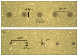
High-speed via drilling can be done using a single laser pulse per hole by combining both the high peak power and some-what long pulse duration of the QCW laser. FIGURE 1 shows ~20μm-diameter exit holes drilled on alumina (96% Al203) 635μm thick, at the rate of 300 holes/s and a pitch of 150μm, with the part moving under the beam at a linear speed of 45mm/s. The part was coated prior to machining and cleaned/polished after processing. Laser processing was done using the single-mode QCW fiber laser, with pulse duration around 200μs.
The shorter the laser pulse duration used, the higher the maximum scanning speed can be without hole elongation; therefore, the higher the maximum drilling rate. However, there is an optimum peak power that leads to best hole quality, with optimum pulse energy and pulse duration. Typically, thicker materials require higher pulse energy and/or longer pulses needed to drill through. For example, drilling rates of 750 and 3000 holes/s are achieved on 381- and 100μm-thick alumina (99.6% Al203), respectively, for 20μm exit holes. For a similar via size, a drilling rate of 300 holes/s is achieved for 381μm-thick AlN. Due to its higher thermal conductivity, AlN requires a higher peak power and longer pulse duration to be used to drill holes compared to alumina at the same thickness. Note that similar drilling rates and high quality can be achieved for various types of materials in addition to ceramics, from semiconductors such as silicon to metals such as stainless steel.
Drilling requires good coupling, but also the ability to adjust the size of the holes drilled. High power densities typically result in consistent coupling and hole drilling in materials that couple poorly, such as alumina. However, significantly increasing peak power simply to promote coupling could impact hole quality. In addition, an application may desire larger hole sizes, requiring increased focused spot sizes that reduce the maximum achievable power density. Traditionally, absorbing coatings are used to enhance surface coupling on alumina. IPG Microsystems has developed new methods in which enhanced coupling can be achieved by use of modified laser techniques and no coating is needed to achieve coupling enhancement. However, depending on the particular situation, coatings might still be used to help overall quality by minimizing splatter and dross accumulation.
The hole size machined can be adjusted by changing the diameter of the process fiber (for example, by changing laser and its fiber or by using a beam switcher/coupler connecting the laser feed fiber to a larger process fiber), the beam delivery (varying the collimator and/or objective focal lengths) and process parameters used such as pulse duration and/or pulse energy (i.e. peak power), or relative position of focus plane vs. work-piece surface plane.
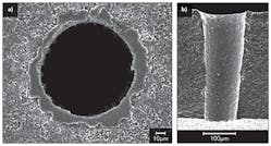
FIGURE 2 shows scanning electron microscopy (SEM) images of ~90μm exit holes drilled using the multimode QCW fiber laser in 381μm-thick AlN, at a rate of over 100 holes/s. Similar results are obtained for 381μm-thick alumina with typical entrance of ~100μm in diameter, and ~70μm in diameter for the exit for over 20,000 holes/part in packaging applications.Typical positional accuracy achieved is within ±5μm over an area of 150 × 150mm, with the hole diameter variation better than 15% of nominal hole size for 100% of the holes. Both periodic and non-periodic hole patterns can be machined at high speed with high positional and dimensional accuracy, by using external encoder-based laser triggering.
A similar setup used for drilling can also be used for high-speed scribing on these ceramics, where a single pulse is used to machine a blind hole into the material, with an appropriate pulse-to-pulse spacing needed to allow for a follow on breaking operation.
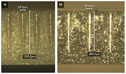
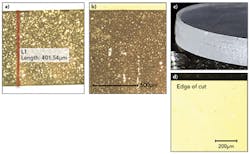
FIGURE 3 shows scribing of alumina (99.6% Al203) and AlN 381μm thick, both at a speed of 300mm/s, and using a pulse duration below 50μs. Scribing of alumina 635μm thick can be done using a longer pulse duration around 100μs at a speed of 200mm/s with individual pulses each leading to a depth over 350μm.Cutting with QCW fiber laser
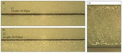
The QCW fiber laser also allows for high-speed and -quality cutting of ceramics with no dross or chip-out. High-speed cutting of 635μm-thick alumina was demonstrated at 140mm/s using the single-mode QCW laser, while 381μm-thick alumina was cut at a linear speed of 250mm/s (FIGURE 4). A coating was applied prior to the process and removed afterwards, helping to protect from spatter and recast.These results demonstrate why the QCW fiber laser is displacing the CO2 laser in the machining of ceramics such as alumina and AlN, allowing for higher throughputs and, because it can easily be focused to spot sizes below 50μm in diameter, machining of smaller vias and finer structuring. On the other hand, compared against shorter-pulse-duration lasers operating in the nanosecond or picosecond regime, the QCW laser often allows for much higher throughput due to its higher removal rates, while still achieving adequate machining quality.
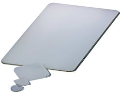
Recently, cutting of sapphire has been the focus of considerable attention because of its use in mobile phones. FIGURE 5 shows some of the typical shapes cut for the consumer electronics market using the QCW fiber laser.Laser workstation
Depending on the material and the application, process development establishes which laser and laser technique is better suited to meet manufacturing goals, thus allowing for specification of equipment options. In addition to required machining quality, including dimensional and positional specifications, additional considerations for high-volume manufacturing include throughput needs as well as cost of ownership.
To address these multiple and at times very distinct requirements, the laser workstations are tailored to the final specifications needs, namely in terms of positional and dimensional specifications and throughput. IPG Microsystems provides a series of workstations in which multiple laser types and beam delivery systems can be installed and are available for immediate sequential use. For example sapphire can be cut using a QCW fiber laser coupled to a high-gas-pressure cutting head, followed immediately by processing with a pulsed picosecond laser using a galvanometer-based machining approach to bevel or polish the edges of the machined piece.
Conclusions
A new generation of QCW fiber lasers enables high throughput drilling, scribing, and cutting of materials up to several millimeters thick with high quality typical of micromachining needs. The high beam quality allows for small spots on target with high power densities, leading to coupling in materials that are typically transparent at NIR wavelengths, such as alumina and sapphire. If larger spots are required, then there are processing techniques that still allow for 100% coupling to these materials. High drilling rates of 300, 750 and 3000 holes/s were achieved on 635-, 381-, and 100μm-thick alumina, respectively; high-speed scribing at 200 and 300mm/s was demonstrated for 635- and 381μm-thick alumina; and high cutting speeds were demonstrated on 635- and 381μm-thick alumina at 140 and 250mm/s, with negligible dross and no chip-out. Similar results were shown for AlN, but typically with a relatively lower throughput. Sapphire with thicknesses of 0.4, 1, and 3mm were cut at speeds around 12, 9, and 3mm/s, with final speeds depending on geometry and quality requirements.
QCW fiber lasers can be combined with advanced workstations to drive high-volume, high-accuracy laser manufacturing in a variety of markets, from packaging to consumer electronics.
ACKNOWLEDGEMENTS
The authors express their appreciation to the following people for their assistance in preparing this article: Cristian Porneala, Xiangyang Song, Mathew Hannon, Dana Sercel, Sean Dennigan, Heath Chaplin, John Bickley, and Jeff Sercel.
