In a laser scanning system, a laser beam is focused and the resulting spot scanned to move along a line (or with two scanning mirrors, anywhere in a plane); such systems can be made to engrave images into metal or accomplish other laser-machining goals such as cutting or drilling. Laser scanning mirrors—for example, a galvanometer or a polygon scanner—often produce a beam whose angle theta (θ) changes linearly with time. However, when such a beam is sent through an ordinary focusing lens, the result is a spot whose position at the image plane changes nonlinearly with time, leading to variations in received laser energy per unit area.
To solve this problem, an “f-theta” lens is specially designed so that the position of a point in the image field scales linearly with the lens’ input scan angle θ, meaning that the angle of a scanning polygon or mirror on the input side is directly proportional to field position on the output side. This is a valuable property for any scanning optical system, for materials processing and otherwise. An f-theta lens also has a flat field to accommodate the entire scan area.
The following is a sampling of various types of f-theta lenses and scanning systems on the market.
Telecentric or nontelecentric?
An f-theta lens that is telecentric has one additional characteristic: all chief rays on the image side of the lens are parallel to the optical axis. As a result, the position of the focused spot does not shift laterally if the metal plate to be engraved (for example) drifts away from the focal plane of the lens. Because telecentric lenses are larger, heavier, and more expensive than their nontelecentric counterparts, they should only be used when needed (when it is known that the workpiece or laser/optics can shift enough to move the laser spot position out of spec).
Sill Optics (Wendelstein, Germany), which produces scan lenses for ultraviolet (UV), visible, and infrared (IR) lasers (both standard and ultrafast), offers both telecentric scan lenses with a perpendicular beam incidence and nontelecentric lenses with high scan fields. One can also distinguish between fused-silica and optical glass lenses, which are often the cost-effective alternative. For high-power lasers, fused-silica lenses are necessary; the low coefficient of thermal expansion and the low dependence of refractive index on temperature of fused silica result in a minimal thermal focus shift.
For the design of polychromatic lenses, different optical glasses must be used to correct lateral and chromatic color shift. Applications for these scan lenses include processes with online observation, and any process using ultrashort-pulsed lasers. Femtosecond lasers have a broader wavelength spectrum than standard lasers due to their short pulses. It should be noted that the power of one femtosecond pulse can be high enough to destroy lenses with low-cost glasses or internal back reflections.1
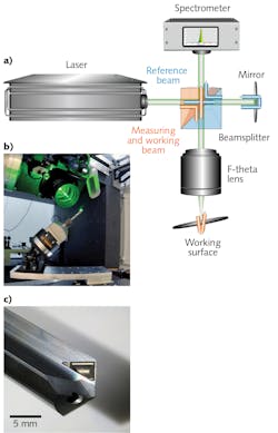
An example of a polychromatic lens for ultrashort-pulsed lasers is the S4LFT7012/292 by Sill Optics, which was developed during a European Horizon 2020 research project called ADALAM. The goal was to create a sensor-based adaptive laser micromachining process with online topography measurement consisting of a spectrometer, a mirror, a beamsplitter, and the scan lens itself integrated into the system.
The incoming beam is split into a working and a reference beam, with the working beam passing through the scan lens and focused on the working surface. The reflected portion of the beam is used for topography measurement at the spectrometer; a mirror also reflects the reference beam to the spectrometer. The wavelength difference between the beams gives information on the path length and thus the height profile of the working surface (see Fig. 1). This is akin to an optical coherence tomography (OCT) measurement.
An ultrashort-pulse laser with a wavelength range of 540 to 590 nm was used for this application. The scan lens for this application must be both color-corrected and ultrashort-pulse capable. The lateral color shift (here, 5 µm) and the chromatic focal shift (here, 30 µm) were minimized by an optimal lens design.
Standard micromachining with ultrashort-pulse lasers is an accurate and reproducible process, but pockets with a depth of some hundreds of microns show significant errors. The adaptive laser process that was developed and tested in the ADALAM project is a solution for challenges like this. To see how well it worked, a chip-breaker structure on a carbide drill was manufactured. Using adaptive microdrilling enabled an increase in depth accuracy of a factor of about five in comparison to nonadaptive laser processes.2 The S4LFT7012/292 is now a standard product of Sill Optics.
Wide range of wavelengths
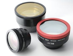
F-theta lenses are used at wavelengths across the optical spectrum. II-VI (Saxonburg, PA) produces a portfolio of f-theta lenses that cover wavelengths from the UV to the far-IR (from 266 nm to 14 µm) for a wide range of industrial lasers, says Je Sun Oh, product line manager, microprocessing laser optics at II-VI (see Fig. 2). “II-VI’s f-theta lenses enable a variety of materials-processing applications including welding, cutting, marking, scribing or engraving of metals, plastics, carbon fibers, and glass,” she notes. “Other applications include laser surface treatments and additive manufacturing.”II-VI combines zinc sulfide multispectral optics with fused-silica optics to achieve small and light scan lenses operating at a 1 µm wavelength that enable faster OLED film cutting with fiber lasers, says Oh. The company also developed a housing design to seal scan lenses and achieve very high transmission at a 5 µm wavelength, enabling curved cutting and fine microdrilling of glass panels with carbon monoxide (CO) lasers, which operate at around 5 µm.
Micro- and macromachining
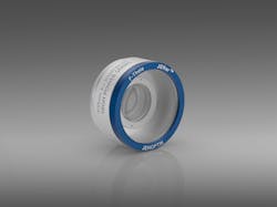
Industrial applications require components that are industrially hardened, as well as that have the ability to be swapped out quickly. “F-theta lenses from Jenoptik fulfill the requirements of almost all standard methods for micro and macro laser materials processing,” says Dr. Maria Oliva, Director Global Product Management Semiconductor & Advanced Manufacturing at Jenoptik Optical Systems. “Our product portfolio includes f-theta scan lenses for almost all common wavelengths and geometries [see Fig. 3].” Oliva notes that the lenses do not require additional cooling, even at high laser powers.The adhesive-free mounting technology also contributes to the long-term stability of high-performance optics, and also provides investment security, says Oliva. Each individual lens is checked for cleanliness, performance, and transmission. For applications that require a lens change, it is possible to replace Jenoptik lenses (of the same type) without making major adjustments to the laser system. An individually replaceable protective glass is also provided for each f-theta lens.
The company’s new telecentric f-theta lens for use at a 355 nm wavelength can be used for a wide range of high-accuracy laser applications. “The short lens focus enables a small spot diameter in a scan field of 22 millimeters. Depending on the application, spot sizes of up to 4.5 micrometers are possible. Jenoptik developed a high-accuracy mounting technology for precise adjustment, Oliva explains. “It is optimized for micromachining applications in microtechnology, electronics, and the display market. In particular, the very small telecentricity angle allows unprecedented accuracy and application quality. Due to its very small spot size and high telecentricity, the lens is optimally suited for high-accuracy drilling applications, especially through-hole via drilling in printed-circuit boards. The large scan field in turn allows an additional increase in throughput.”
Systems with f-theta lenses
Scanlab (Puchheim, Germany) is a company that does not manufacture scanning lenses itself, but instead integrates scanning lenses, including f-theta lenses, from various manufacturers into complete laser systems produced by Scanlab.
“Key quality indicators of good f-theta objectives are low field curvature, a large image field, low thermal shift if used with high-power lasers, and good, homogenous focus quality throughout the entire image field,” says Florian Merkt, systems engineer at Scanlab. “To assure best performance in various applications, intense collaboration with our suppliers often begins before a scan solution’s design is started. At an early stage, simulations are used to evaluate performance in combination with specific scan heads. Later on, tests of scanning lens samples in our laser labs yield verification of properties, such as transmission at the laser wavelength, quality, and homogeneity of the spot in the working plane or confirmation of the distortion correction.”
Integration of scanning lenses at Scanlab consists of the optimized mechanical mounting of f-theta lenses in the various versions of its scan heads. “Here, it’s crucial that the design mirror distances are met in order to guarantee best imaging quality and a sufficiently large field size,” says Merkt. “Another important aspect is to derive the correct distortion correction from optical models of the scanning lenses and to integrate this correction in the control scheme of the scan system.”
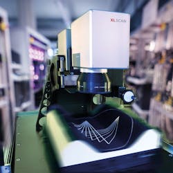
Often, scanning lenses are combined with z-shifters (for example, Scanlab’s varioSCAN or excelliSHIFT) to achieve a three-dimensional scan volume (see Fig. 4). While the f-theta lens delivers the flat-field correction, the z-axis allows moving the focus along the beam path and hence can shift the working plane above or below the plane defined by the f-theta lens. In this case, an even more sophisticated 3D correction for scan-head control is needed in order to steer the laser focus to the desired XYZ position.While the position in the working plane of a spot produced by an f-theta lens approximates the f-theta condition (meaning the image height is approximately proportional to the set scan angle,) deviations from this proportionality can be compensated by controlling the scan mirrors, notes Merkt.
Scanlab’s systems cover a wavelength range from 193 nm to 10.6 µm. As a result, any example applications can only give a glimpse of the true variety of processes in which f-theta lenses are used. In many laser marking processes at low power levels, scan speed is the key. In some of these applications, CO2 lasers are focused by simple single-element scanning lenses to yield spot sizes of a few hundred micrometers.
In contrast to the first example, plastic welding with diode lasers allows joining transparent and opaque plastic parts at moderate power. Usually, the image size is rather large and therefore long focal lengths are needed, while the spot size is less critical.
A third application could be laser welding of steel with high-power fiber lasers exceeding 1 kW. The corresponding scan lens designs must be optimized for low absorption.
As Merkt explains, in micromachining, f-theta lenses are used, in particular ones with a short focal length. These lenses help achieve the smallest spot sizes and allow fine engraving and structuring of diverse substrates, including micro-optics.
Some customers even combine the scan head and f-theta lens with diffractive optical elements to shape the spot in the image plane, says Merkt.
ACKNOWLEDGEMENT
The following people contributed to the Sill Optics section: Cornelia Halbhuber and Manuel Zenz of Sill Optics, Albert Borremann of Demcon, Max Groenendijk of Lightmotif, and Rouwen Kunze of Fraunhofer IPT.
REFERENCES
1. G. Toesko and C. Dehnert, “Femtosecond laser optics combat pulse dispersion, color errors, and reflections,” Laser Focus World, 52, 3, 38–41 (2016); http://bit.ly/FThetaRef1.
2. M. Zenz et al., Mikroniek, 59, 4, 12 (2019).
For more information
Companies mentioned in this article include:
II-VI
Saxonburg, PA
Jenoptik Optical Systems
Jupiter, FL
www.jenoptik.us/products/optical-systems
Scanlab
Puchheim, Germany
Sill Optics
Wendelstein, Germany


