It is true that sophisticated optical systems were routinely designed before the advent of lens-design software: exquisitely capable microscopes, telescopes, camera lenses, and other optics designed by hand calculation served their purpose well. But fast computer calculation now allows the lens designer to find optimized solutions for very complex optical systems to take into account, to a highly precise degree, the effects of glass, fabrication, and mechanical imperfections; to easily add aspheric surfaces that reduce the number of elements, widen the field, and/or add other benefits; and so on. As a result, skilled lens designers working closely with skilled optics fabricators now produce precision optics for purposes ranging from smartphone cameras to military infrared (IR) imaging, computer chipmaking, augmented/virtual reality (AR/VR), and many others.
A typical optical-design software package can model an optical system via ray-tracing (with spot diagrams as the visual) or via wave-based physical optics calculations (with diffraction patterns as the visual), with the latter requiring more calculation. Imaging lens-design software has numerous offshoots, including nonimaging optical-design software, integrated CAD/CAM programs, and other derivatives, some or all of which may be incorporated into the original software package. This article provides a bit of background on some commercial examples of current lens-design software packages.
Advanced ray tracing
OSLO (Optics Software for Layout and Optimization) is optical-design software produced by Lambda Research Corporation (Littleton, MA) that facilitates design and analysis of a large variety of optical systems. As described by Ed Freniere, the company’s president, the core of the program is a sequential ray-trace engine with geometrical and physical-optics modeling capability. “OSLO includes numerous local and global optimization methods to design simple and complex imaging systems,” says Freniere. “OSLO has built-in tolerance analysis and simulation capability and a nonsequential ray-trace analysis kernel for systems requiring varying surface intersection capability. OSLO is open-architecture and very flexible, includes a vast number of surface types and optimization targets, and also has a high-speed macro-language and a fully integrated compiled programming language for data generation and analysis.”
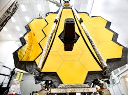
According to Freniere, OSLO’s fundamental strength is advanced ray-tracing, which is key to designing zoom systems where the need for tracing efficiency is paramount. He adds that this capability was key, for example, in the design development of a 300:1 zoom lens. OSLO’s ray-tracing efficiency has also facilitated designing and analyzing systems where many rays are needed, such as photolithographic lenses. OSLO has built-in aperture functions and has been used for designing and modeling of segmented mirror systems, including the James Webb Space Telescope (see Fig. 1). The software package also contains coordinate transformations and aspheric capability with optimization that makes off-axis systems such as three-mirror anastigmats and tolerance analysis much simpler, Freniere notes.
CAD integration
Used for the analysis, design, optimization, and tolerancing of optical components, subassemblies, and full systems, OpticStudio, which is produced by Zemax (Kirkland, WA), can simulate both imaging and nonimaging (lighting and illumination) systems. OpticStudio is built around the capability for modeling systems in which the assumptions of geometric optics hold—namely, cases in which the optical components in the system are much larger than the wavelength of light propagating through the system, thus allowing light to be modeled as geometric rays. However, the software does support diffraction-based calculations (based on Fourier and Huygens theory) and can also model free-space coherent propagation of light (using Fresnel and Fraunhofer theory) that is useful for many applications (such as laser scanning or fiber coupling). Recent additions provide support for characterizing micro-optic components within larger macroscopic optical systems (such as surface-relief gratings in an AR headset).
Beyond the initial setup and analysis of a given design, OpticStudio has the ability for parametric optimization of systems to achieve best as-built performance of a given design. Recent additions to the software also allow for optimization of discrete data used to describe surface geometry, providing greater flexibility of freeform design. Validation of the as-built performance is done using robust tolerance analysis to characterize the effects of perturbations on system performance, allowing for these perturbations to be compensated during design production and assembly. As noted by engineers at Zemax, upcoming features will provide the ability to obtain quick, approximate results for expected production yield that can be used during the design process.
Once the optical design is completed, it can be moved into computer-aided design (CAD) for optomechanical packaging and assembly using OpticsBuilder, which allows the geometry of the optical model to be accurately recreated in the CAD platform automatically. The optical components are not brought in as static CAD parts, but are recreated as native CAD objects. This tool, which is currently supported for the SolidWorks and Creo Parametric CAD programs, also allows the optical performance of the full optomechanical assembly to be analyzed directly in CAD, as the software uses the same ray-tracing engine as provided in OpticStudio. The impact of the mechanical packaging and assembly can thus be directly modeled in the platform in which the optomechanics are being defined. Once the system is ready for production, OpticsBuilder then supports the ability to create manufacturing drawings automatically, pulling required data from the optical and mechanical models.
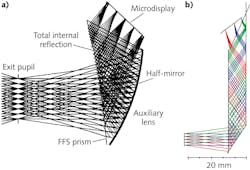
An interesting example of using OpticStudio is in the design of a displays for an AR/VR headset. Current designs are based on competing technologies—freeform optics vs. diffractive optics. An example of an optical see-through head-mounted display (OST-HMD) design using freeform optics based on U.S. Patent 2014/0009845 A1 is shown in Figure 2a. The main optical component in this system is a freeform prism. While a complete description of the prism requires a 3D model, the ray-tracing properties of the prism can be accurately characterized in the surface-based sequential mode of OpticStudio using Coordinate Breaks. Doing so allows for fast setup, design, optimization, and tolerancing of the model. The sequential model can then be moved to the nonsequential mode of OpticStudio for complete 3D analysis, including characterization of the effects of stray light or scattering on system performance. Either the sequential or nonsequential model can then be directly transferred to CAD for optomechanical packaging using OpticsBuilder.The geometry of the prism surfaces in this case can be described using a variety of parametric descriptions, but also using discrete data in the form of a Grid Sag surface. Using the multiple configuration modeling of OpticStudio allows the see-through and projection paths of the OST-HMD to be simultaneously optimized and designed.
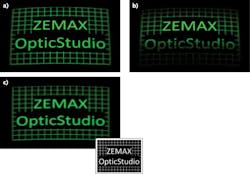
An example of a headset design using diffractive optics is shown in Figure 2b. This design includes a hologram coupling light into a waveguide that then propagates light from the display into the eye. OpticStudio supports the ability to model idealized as well as realistic holograms (the latter using the software’s optically fabricated hologram surface); here, the model is again created in sequential mode using Coordinate Breaks to mimic the full 3D geometry. The boundary constraints provided in the Merit Function Editor of OpticStudio are also used to ensure a physical geometry for the model. Computations based on Kogelnik theory can then be used to calculate the efficiency of the waveguide as a function field and source polarization, allowing the design to be optimized for those input conditions. An example of ignoring and then considering the efficiency of the waveguide can be seen in Figure 3. OpticStudio also supports the ability to model diffractive components using rigorous coupled wave analysis (RCWA).Choosing surfaces as aspheres
CODE V by Synopsys (Mountain View, CA) is an optical design and computational engineering package that is used to model and analyze image-forming systems. CODE V enables engineers to design and optimize optical systems for best-possible performance and manufacturability—for example, engineers can include tolerance desensitization during CODE V optimization to produce designs that are easiest to fabricate with the highest production yields.
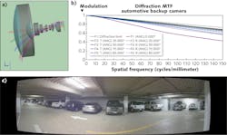
“As one example of how CODE V helps solve optical-design challenges, consider the complex performance and fabrication requirements of a compact automotive backup camera,” says Matt Novak, CODE V senior customer applications engineer. These camera modules are built in high volume and require easy assembly with little to no adjustment, he notes. In addition, the design should provide excellent imaging performance despite the wide field of view and compact packaging, and account for the fabrication and assembly tolerances.
“CODE V offers designers a powerful optimization engine to create a practical working design for the backup camera, as well as tools that offer built-in engineering expertise—such as the Asphere Expert and Glass Expert,” says Novak. In the design example shown in Figure 4, Asphere Expert identified the two most effective surfaces to fabricate as aspheres (nonspherical) to improve optical aberration correction. The Glass Expert tool selected an optimum set of moldable glasses to maximize the correction of chromatic aberrations.The Asphere Expert and Glass Expert tools enabled the final design to meet packaging and performance requirements; use readily available, cost-effective materials; and control the aspheric surfaces on elements according to manufacturing best practices for slope and aspheric departure.
Software for beginning designers
In contrast to the large and complex software packages that require an expert’s knowledge to fully profit from, a smaller lens-design program available from Excelitas Technologies (Waltham, MA) called Winlens is aimed at students and engineers with less experience. The software has a long history: WinLens v1 was written at the time of the transition from DOS to Windows 3. “At that time, there were quite a few very powerful mainframe or DOS lens design programs available, however they were not user-friendly; they were very rigid in operation and heavily numbers oriented with graphics being an occasional luxury,” says Patrick Janassek, Product Manager, Catalog, at Excelitas. “It took a full-time lens designer to use them well. Operations that should be simple, like turning a component round, were very difficult and required manual editing of each surface and glass in that element.”
Janassek explains that Windows 3 and new software development tools offered an opportunity to follow a different, much more flexible path that would work for new students and optical engineers and still offer serious tools for full-time designers. “It was important for students and lecturers to be able to easily setup and tweak simple systems, to see the effects immediately, and to display optical data in meaningful ways—for example, to display lens data and calculations in more meaningful ways. Previously, optical glass data was only available in large catalogs full of tables of refractive index and transmission values—but Windows offered the opportunity to display this graphically and at non-standard wavebands,” he says.
Around that time, Spindler & Hoyer’s Microbench (which today is LINOS Microbench) system—a high-precision optical cage system for complex optical setups—offered a whole range of optical components such as singlets and doublets for which the design data was available. All these conditions set the stage for Excelitas to develop a program that would allow users to mock up systems of LINOS Microbench parts using only the part numbers, to model complete custom optics or a combination of the two types, making simple things like editing, analyzing, and comparing easy and providing insight and understanding. The first result, WinLens v1, was very limited—working only with centered LINOS Microbench lenses.
Version 2 allowed users to define their own lenses and mirrors so that they could analyze custom systems. Over the years, the program has been enhanced in ways both large and small: transmission calculations, zoom, systems optimization (see Fig. 5), ghost analysis, 3D features such as tilt and decenters, Gaussian beam calculations, custom coatings, editing tools, bookmarking, multiple copies of graphs for comparisons, and others. One theme in particular has been the addition of tools for selecting glasses, culminating with a customizable interactive glasses plot.“The aim has never been to be at the cutting edge of optics, but to provide a good user-friendly set of tools for our customers,” says Janassek. “Even when creating specialized tools for designers in research and development teams, special consideration is taken to ensure that these tools are flexible and accessible to the less experienced user.”
Excelitas has always offered a free version, WinLens3DBasic, widely used in universities for optical education and rudimentary optical design. This program does not have optimization or ghost analysis, but includes everything else. Both WinLens3D and Winlens3DBasic [free] are used in universities for teaching as well as in companies for optical designing or testing. The professional suite also includes a Tolerancing program with ISO10100 drawings and Glass Manager and Material Editor programs.
For More Information
Companies mentioned in this article include:
Excelitas Technologies
Waltham, MA
Lambda Research Corporation
Littleton, MA
Synopsys
Mountain View, CA
Zemax
Kirkland, WA


