Many advanced commercial and military applications require ultra-low-loss films that are extremely difficult to deposit using conventional electron-beam or ion-assisted deposition (IAD). Mirrors used in ring-laser gyroscopes (RLGs), for instance, require high packing density, minimal defects, and negligible absorption. These same characteristics are also instrumental in the production of high-damage-threshold optics. We have explored dual ion-beam sputter deposition as an alternative and present data for RLG mirrors deposited using a commercial system (see Fig. 1).
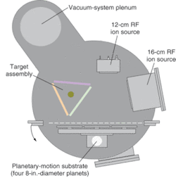
The deposition system used for these experiments is a dual ion-beam deposition (DIBD) batch (nonloadlocked) system equipped with a fully automated state-of-the-art software control package. At the core of the system are two radio frequency (RF)-type gridded ion sources. These sources provide excellent beam-current control and dramatically improve mean time between maintenance (MTBM) over alternative technologies (see Fig. 2).
Film deposition is achieved using the 16-cm-diameter RF ion source. The ions from this source are accelerated through a series of biased grid optics, toward the target.1 The energy of these ions is sufficient to cause sputtering of the target material. This sputtered material is highly energetic and therefore generates films with excellent adhesion and high packing density. The 12-cm-diameter RF assist source is focused on the substrate and primarily serves to modify film stoichiometry, alleviate stress, and perform an in situ substrate preclean. These two sources operate in unison to produce films with optimal optical and physical properties.
Sample application
Low-loss mirrors are crucial components of RLGs used for inertial navigation systems. The cavity of the gyroscope can take many forms, but the most common is that of an equilateral triangle. The HeNe laser cavity has two circulating beams, one rotating in a clockwise direction and the other in a counterclockwise direction. Mirrors are placed at the corners of the triangle with one mirror designed to transmit approximately 1% of the light. The two emerging beams from this mirror are combined to form an interference pattern, which is modulated by a beat frequency proportional to the rate of rotation.
Spectral scatter from the low-loss mirror surface substantially affects the RLG system performance. The degree of scatter is a major contributor to a phenomenon called “lock-in.” Lock-in occurs when the rotation rate is small, leading to a diminishing frequency difference between the clockwise and counterclockwise beams. The effect is due to the interaction of the two beams when a small amount of reflected light is scattered back into the oppositely traveling beam. When the frequency difference becomes too small the counter-propagating beams lock together giving a beat frequency of zero, thus showing no change in rotation when in reality there is.
Another performance limitation for the RLG system is absorption. Absorption must be minimized to achieve the best possible signal-to-noise ratio. In addition, the lower the absorption, the higher the level of finesse that is attainable for the mirrors. For these reasons the mirrors must be manufactured with extremely low quantities of defects and losses to optimize the performance of the RLG system.
Low-loss-mirror design
To support the optical geometry and HeNe laser frequency of choice, the optical thickness of the RLG mirrors is designed to provide a maximum reflection at 632.8-nm s-polarization with a 45° incident angle. While many materials can be deposited with the system, the materials used for this application were silicon dioxide (SiO2), tantalum (Ta), and titanium (Ti). The metal targets are sputtered reactively to produce the desired high-refractive-index oxides, namely tantalum pentoxide (Ta2O5) or titanium dioxide (TiO2).
Two sets of mirrors with a nominal target reflectance of 99.9995% were produced with one set from quarter-wave stacks of SiO2 and Ta2O5 (samples 1758 and 1790) and another set using quarter-wave stacks of SiO2 and TiO2 (samples 1674 and 1675). Both sets of mirrors used the same number of layers so direct comparisons could be made. Overall losses and surface roughness measurements were performed on both sets of samples.
Process preparation
Clean substrates and a low-particle-density manufacturing environment are critical to successfully produce low-scatter and low-absorption films. Small particles on the surface of the substrates prior to deposition effectively grow through the deposition of film layers, which in turn exacerbate light-scatter and negatively affect overall loss. For this reason the DIBD system was operated in a class-100 clean room where all samples were washed using a spin cleaner and high-purity isopropyl alcohol. Once clean, the substrates were blown off with a dry-nitrogen gun equipped with a 0.2-µm filter and static neutralizer. This process eliminated the surface charge on the substrate, thereby reducing electrostatic attraction of nearby particles. Finally, special care was taken in preparing the vacuum chamber for low particle generation as an added step to minimize in situ substrate contamination.
Loss measurement
The exceptionally high reflectance of these mirrors requires use of special loss-measurement metrology. Total loss and transmission values were determined using laser cavity ring-down. In addition, surface-scatter measurements were performed using the total-integrated scatter technique. The cavity-ring-down method is a technique that measures the time rate of decay of a light pulse trapped in an optical cavity.
The optical cavity is composed of two or more highly reflective mirrors. As the light bounces back and forth inside the cavity a small portion is transmitted through each mirror. This transmitted light is monitored at one of the mirrors as a function of time. The resulting exponential signal decay (I) can be expressed as
I = Ioexp[−(1−R)tc/2L]
Where (Io) is the initial signal magnitude, (1-R) is the cumulative transmission through the mirrors assuming no absorption or scatter, (t) is time, (c) is the speed of light, and (L) is the cavity length.
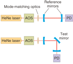
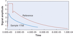
To measure the total losses of a sample, the first step is to measure its transmission at a 45° incident-angle s-polarization. Next, two standardized mirrors, of known optical properties, are used to characterize the total loss of a reference cavity. Finally, the sample mirror is introduced into the cavity (see Fig. 3). Although the geometry of the cavity is different from the reference, the total cavity length and incident angle on the reference mirrors is the same and thus associated losses are constant. The total decay time is then remeasured. Subtracting out the total loss of the reference cavity, the transmission loss of the sample mirror, and the surface scatter gives the absorption of the sample (see Fig. 4).2-4 Final loss results for all samples are in parts per million (see table).
Some important points to mention are the observed differences in the total loss and transmissions between the mirrors deposited using Ta2O5 versus TiO2 for the high-index material. The lower losses in the Ta2O5 mirrors were expected because of the inherently higher losses of TiO2 films and the associated differences in process conditions used for deposition. The lower transmission values of the TiO2 mirrors were expected because of the higher TiO2 index relative to Ta2O5, resulting in a higher degree of reflection, given the same number of quarter-wave stacks.
Surface roughness
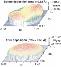
Rough surfaces typically indicate a higher degree of columnar growth and growth nuclei, whereas smooth surfaces tend to be characteristic of a dense microstructure and low defect densities. To accurately measure the surface profile of the deposited film, all mirrors were deposited on precharacterized, super-polished zerodur (Schott Glass Technologies; Mainz, Germany). This allowed us to compare the surface before and after coating (see Fig. 5).
The type of substrate fixture used during deposition created a shadow around the edge of the substrate, the measured surface roughness after deposition was within the standard error limits of the metrology, 0.52 Å versus 0.53 Å. This signifies that the deposited films have a sufficient amount of densification and quality to replicate the original surface roughness.
Conventional manufacturing equipment such as electron-beam, magnetron, or ion-assisted-deposition technologies are often inadequate for manufacturing films of the caliber required for many current and emerging industrial and military applications. In contrast, dual ion-beam-deposition systems have proven their capability to produce mirrors with losses lower than 5 ppm and with film packing densities sufficient to maintain predeposition substrate rms values.
REFERENCES
1. H. R. Kaufman, R. S. Robinson, Operation of Broad-Beam Sources, Colorado: Commonwealth Scientific Corp. (1987).
2. C. J. Hood, H. J. Kimble, J. Ye, Phys. Rev. A 64, 033804 (2001).
3. K. W. Busch, A. M. Busch, eds. Cavity-Ringdown Spectroscopy (ACS Symp. Series) 720 (Washington, DC; American Chemical Society; 1999).
4. R. G. Berden, M. G. Peeters, Int. Rev. Phys. Chem. 19, 565 (2000).


