ROLLAND ZELENY
As new lasers and laser-friendly materials are introduced, the number of laser-based materials-processing applications continues to expand. To meet the needs of these new applications, laser-system designers require a broad range of beam-positioning architectures.
Moving a focused laser spot within a two- or three-dimensional space can be accomplished using several different laser-beam-positioning schemes. Common examples are the two-axis pre-objective scan head, the three-axis post-objective scan head, and x-y plotters. Selecting an appropriate beam positioning and scanning mechanism is an important consideration in any laser-based system. Frequently, a laser system designer has more than one solution available for a given application. Several technical issues should be considered when selecting an optimized solution.
Scanner types
A post-objective scanning architecture is one in which a two-dimensional x-y scanning mechanism is placed after a movable expander lens and a focusing objective lens. The scanning mechanisms used are most often galvanometers with reflective mirrors attached, which can address a specific field size in two or three dimensions.
Another widely used approach to laser scanning is the two-axis pre-objective scan head, in which the x and y scanners are placed in the beam path before the focusing objective lens. This objective lens is often referred to as an f-theta lens or field-flattening lens. These heads are used in a broad number of applications with small- to medium-size scan fields. They are often selected when speed is the most-important consideration. There are limitations with this architecture. Because of cost and size limitations of the output objective lens, two-axis scan heads have beam-aperture limitations, which limit their ability to produce small laser spot sizes over medium-size scan fields. A given pre-objective scan head offers no flexibility in working distance, field size, and laser spot size. In applications requiring larger field sizes, smaller laser spot sizes, or the need to vary these parameters, a post-objective three-axis architecture has distinct advantages.
The x-y plotter has the advantage of an on-axis optical system. In this case, a very small spot size can be produced and moved over very large fields. There are few optical aberrations, which are present to a small extent in both two- and three-axis scan heads. These systems are often large, however, and suffer from slow scan speeds. Although used in a variety of applications, these factors limit the number of applications that can be addressed.
Post-objective scanning with a three-axis scan head offers the designer much of the speed advantage of a two-axis system. It can produce a small spot size and scan large field sizes like the x-y plotter. It can address three-dimensional objects. It is appropriate for a wide range of laser wavelengths and some models offer the flexibility to adjust field size and spot size. These heads are used in marking, cutting, drilling, rapid prototyping, and imaging applications on a variety of materials including glass, wood, textiles, metals, tiles, stone, paper, photo-sensitive plates, and other materials. An emerging application for these heads is the processing of a three-dimensional work surface.
Theory of operation
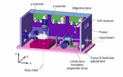
In a post-objective three-axis scanning arrangement, the laser beam first enters an expander lens (see Fig. 1). Some manufactures will match the expander lens to the laser-beam parameters, usually eliminating the need for a costly beam expander. After the expander lens, the beam diverges rapidly until it enters a second focusing objective lens. The beam, now converging, passes through and is steered by a set of x and y mirrors that are coupled to galvanometers. The orthogonal arrangement of the x and y mirrors directs the beam down toward the workpiece and over the length and width of the scan field.
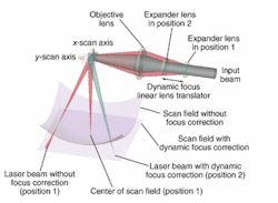
In a scan head without focus correction, the focused laser spot at the center of the field describes an arc when moved in either axis, creating a sphere of focused points above the scan field (see Fig. 2). At locations away from the center of the scan field, the laser beam is not focused. This is a result of the increased length from the objective lens to the work piece as the scanners direct the beam away from the center of the field. In a pre-objective two-axis scan head "field flattening" or focus correction is accomplished using a specially designed objective lens after the scanners. In a post-objective three-axis scan head focus compensation is accomplished by slight adjustments in the distance between the expander lens and the objective lens, in real time, as the scanners direct the beam across the scan field.The distance between the expander lens and the objective lens is adjusted in real time by a third moving z axis—hence the name "three-axis scan head." The expander lens may be moved by a galvanometer-based rotary-to-linear actuator or by a linear voice coil. This linear lens translator requires reasonable bandwidth to keep up with the x-y scanning. As the expander lens moves closer and further from the objective lens, the focal point of the laser is adjusted to keep the focused spot on the scan field at all x and y locations within that field.
Control of the third axis is typically accomplished using software, which addresses a lookup table containing focus-correction values or by using a polynomial equation that commands the linear lens translator to a location proportional to the x-y distance from the center of the scan field. The result is continuous focus correction throughout the scan field.
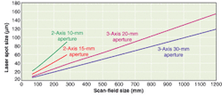
In the three-axis scan head, the post-objective scan mirrors can be larger than in typical two-axis scan heads; thus, the aperture can be significantly larger too. This increased size allows for the use of larger numerical apertures and thus smaller spot sizes (see Fig. 3).Another advantage found in some three-axis scan heads is the ability to offset the nominal distance between the expander lens and the objective lens by repositioning the linear lens translator, allowing the user to change the working distance, field, and spot size with the same scan head. This feature is an added advantage if different applications are being run with the same system in a job-shop setting or if the user wants to experiment with different field and laser spot sizes for a new application. In general, the laser spot size will increase linearly with increased field size. If the field size is doubled, the spot size will double too.
Optical considerations
Along with the advantages of a three-axis scan head, there are some issues that also need to be considered. Most three-axis scan heads can scan ±20° optical across the field in two dimensions. As the beam is steered away from the center of the scan field, the angle of incidence between the beam and the work piece departs from normal. This causes two effects: an increasingly elliptical laser spot on the workpiece, and increasing angles of incidence as the scan angle increases away from the center of the field. An elliptical laser spot may be intolerable when drilling holes if the hole must be kept round. A non-normal incident angle of the beam to the work piece will cause beveled edges in cutting applications. The system designer must decide to what degree these aberrations may affect the application and make tradeoffs with other advantages such as speed.
Another aberration is small laser spot size changes between the center of the field and the outside corners of the field. This is caused by the slight variations in distance between the expander lens and the objective lens used to correct for focusing throughout the field. The spot size can grow to approximately 15% larger from the center to the corner of the scan field, causing differences in energy density of the laser spot.
Post-objective three-axis scan heads are used in applications requiring larger field sizes and smaller spot sizes than can be achieved with a two-axis scan head. The three-axis scan head has a speed advantage over x-y plotter systems but does present some optical challenges, which may or may not affect a given application.
Some three-axis scan heads offer the advantage of a variable field and spot size adjustment, while others only offer one fixed field size. Some scan heads offer a custom expander lens matched specifically for a given laser and application. This eliminates the need for an additional costly beam expansion element before the scan head. An emerging application for three-axis scan heads is the ability to address three-dimensional objects. Three-dimensional objects can be marked and welded on. This usually necessitates more-sophisticated optical configurations and software.
Rolland Zeleny is vice president of sales and marketing at Nutfield Technology, 49 Range Rd., Windham, NH, 03087, 603-893-6200; www.nutfieldtech.com.


