Changes in the polarization state of a light beam as it is transmitted or reflected by a sample can often provide valuable information on its material and/or surface properties. For example, linearly polarized light reflected by a thin film is usually transformed into an elliptically polarized beam with properties that are determined by the film thickness and index of refraction, in addition to the input wavelength, polarization direction, and angle of incidence.
To extract the useful information from a measurement of this type, the polarization state of the incident and reflected beam must be accurately determined. This process is known as optical ellipsometry—a term that in its correct and broadest sense refers to any measurement of light polarization. Common usage has narrowed this definition somewhat, and it is almost exclusively used to describe the measurement of polarization differences. Thus, a typical optical ellipsometer consists of a source, polarizer for defining an input polarization state, compensator or modulator for varying the polarization in a known manner, and an analyzer for determining the polarization state after interaction with the sample.
In addition to thin-film and surface analysis, ellipsometry is routinely used in the optical manufacturing process. Retardation plates, whose primary function it is to modify the polarization of an input light beam, are often characterized using a laser-based ellipsometer at several stages of the manufacturing process. Data from this instrument, in combination with the known physical properties of the waveplate material, are used to completely specify the performance of the optic.
While the design details of commercial ellipsometers can be fairly complex, the basic operating principles follow directly from the tenets used to describe polarization states and their transformation by an optical system. This article provides a brief overview of Jones calculus, one common technique used to model polarization changes. It also describes the operation of a basic ellipsometer and representative commercial applications.
Matrices describe polarization effects
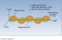
The physical basis of polarization phenomena can be best understood by using the classical wave model of light. In this description, a polarized light beam is represented as a propagating electromagnetic wave (see Fig. 1). If the beam is linearly polarized, the orientation of the electric and magnetic fields in the plane perpendicular to the propagation direction (x-y plane) is constant as the wave moves through space, and the polarization direction is defined by the direction of electric-field oscillation. Thus, the wave in Fig. 1 is polarized in the x direction. In general, linearly polarized light can be oriented at angles between 0° and 180° with respect to the x axis and can be broken down into two in-phase components, one directed along the x axis and one along the y axis.While the concept of linear polarization is adequate to explain the extinction of a light beam by crossed polarizers and similar phenomena, it is a special case of a more generalized polarization description in which the relative phases of the two orthogonal polarization components can take on values between 0° and 180°. For example, circular polarization states are produced by adding equal intensity components with a phase difference of 90°. Elliptical polarization states are produced in cases in which the conditions for linear or circular polarization are not satisfied.
In the general case, an arbitrary polarization state can be described mathematically by
E(x,t) = Ex(0) sin(wt-kz) i + Ey(0) sin (wt-kz + D) j (1)
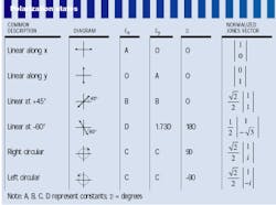
where w is the angular frequency of the light, k is its wave vector (k = 2/l), i and j are the unit vectors along x and y axes, repectively, and D is the angular phase difference between the two components. For most cases, polarization phenomena can be completely described by the intensity amplitudes Ex(0) and Ey(0), in addition to the relative phase angle D. Interaction with a polarization-changing optical component changes the relative magnitudes of one or more of these quantities. For example, a linearly polarized beam incident on a quarter-wave plate at 45° to the crystallographic axes will have D increased by /2, thereby producing a circularly polarized output. The table lists the amplitudes and phase angles for several commonly encountered polarization states.
Mathematically, the variations in amplitude produced by more-complex systems can be modeled using Jones matrices. In this formalism, an arbitrary polarization state is described by a two-element column vector whose elements contain, in a shorthand notation, the amplitude and phase information in Eq. 1. Propagation through an optical component or system is accomplished by multiplying the input vector by a 2 × 2 matrix to generate a product describing the output polarization state. As with other matrix techniques (the ABCD matrices used for Gaussian beam propagation, for example), an overall system matrix is calculated by multiplying the matrices for the individual components together. While there are several different forms for the Jones vector, the following, normalized form is one of the most useful
(2)
Other polarization modeling techniques include Mueller calculus, an alternative matrix technique based on four-element real column vectors and a graphical method based on the Poincaré sphere. While each technique has advantages in the analysis of specific problems, all are capable of treating the propagation of fully polarized light through an optical system consisting of retarders and polarizers. Mueller calculus is uniquely capable of treating the case of a partially polarized input.
Measuring polarization changes
In the most basic sense, an ellipsometer can be thought of as a device used to determine the Jones matrix of an optical system, be it an optical component, surface layer, or spectroscopic sample. In the basic transmission system, a variable polarizer converts light from the source to an input beam with a known and adjustable polarization (see Fig. 2). The output of the variable polarizer is then passed through the sample under study and the output polarization determined using a polarization analyzer. In reflection measurements, similar components are used, but the variable polarizer and analyzer are positioned so that the input beam is reflected by the sample into the analyzer.In the simplest case, there are two orthogonal input polarization states that pass through the system without change (eigenpolarizations). Several common situations, including transmission by a waveplate and reflection from an isotropic surface, satisfy these conditions. In the case of a waveplate, light polarized along the crystalline axes is unchanged; in the reflective example, the eigenpolarizations are parallel and normal to the plane of incidence. In its own frame of reference, the Jones matrix for such a system has the form
(3)
If we use linear polarizers to define the input polarization and analyze the output and a Soliel Babinet compensator to introduce a variable retardation rc , we can calculate the ratio of eigenvalues from a single null measurement using the expression
(4)
where q, g, and d are the angles of the input polarizer, the principal axes of the compensator, and the analyzing polarizer, respectively.2
At least one optics manufacturer uses a system of this type for the routine analysis of waveplates during production. In this case, a polarized input is provided by a laser and the retardation of the compensator adjusted to give a null reading at the output of the analyzer. The basic setup is simple and easy to operate and provides reliable data on fractional retardation. Waveplate order is determined by measuring the thickness of the component and using tabulated birefringence data.
Commercial systems exploit technology
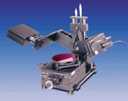
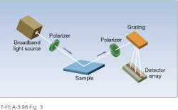
In many materials and thin-film applications, the parameter of interest cannot be determined from a fixed wavelength measurement at a single angle of incidence. To address this problem, spectroscopic ellipsometers have been developed to take data over a wide range of wavelengths and typically have provisions for varying the angle of the input beam and analyzer (see Fig. 3).Typical applications for this type of instrument include the control of compound semiconductors and the characterization of thin films used for ultraviolet lithography applications. In both cases, it is advantageous to have a wide range of source wavelengths in addition to high-speed measurement and processing capabilities. Modern spectroscopic ellipsometers, such as the J. A. Woollam Co. (Lincoln, NE) model M-88, are capable of rapidly recording data at many wavelengths—88 in less than 1 s (see photo at top of this page). Combined with high-speed data-analysis capability, this instrument has successfully been used to control the composition and layer thickness during molecular-beam and metal-organic vapor-phase epitaxial growth.3
The availability of high-speed microcomputers has also opened the door to the ellipsometric characterization of anisotropic materials. In contrast to the simple case discussed above, in which the eigenvectors of the Jones matrix are orthonormal, the analysis of these materials has been too complicated to perform on a routine basis. With increased data-processing capability, however, these measurements are beginning to become practical, thereby creating new applications for ellipsometry.
In general, even the most advanced ellipsometric measurements are comparatively straightforward and inexpensive when compared to alternative techniques. Although the use of a laser source may be preferred in some fixed-wavelength applications, most measurements can be carried out with incoherent light. For example, spectroscopic ellipsometers typically use a white light to provide illumination at a number of wavelengths. Mechanically, variable-angle techniques required the accurate control of the angles between the sample surface and other components, but this is easy to achieve using conventional optical mounting techniques. These properties combined with increased data-processing capabilities make ellipsometry an attractive alternative for many applications in process monitoring and materials characterization.
ACKNOWLEDGMENT
The author would like to thank James Hilfiker of J. A. Woollam Co., Lincoln, NB, for helpful discussions during the preparation of this article.
REFERENCES
1. D. S. Kliger, J. W. Lewis, and C. E. Randall, Polarized Light in Optics and Spectroscopy, Academic Press, San Diego, CA (1990).
2. R. M. A. Azzam and N. M. Bashara, Ellipsometry and Polarized Light, North Holland Elsevier, Amsterdam (1977).
3. B. Johs, J. Hale, and J. Hilfiker, III-V`s Review 10, 39 (1997).


