HENRY SCHEK
Despite broad and varied requirements among biomedical applications, users across the board share a desire for solid-state alternatives to traditional light sources. Because light-emitting diodes (LEDs), the most common solid-state sources, have different optical properties than traditional sources such as xenon discharge lamps, they introduce new constraints for system designers. Fluorescence microscopy craves the many benefits of solid-state light sources, but is one of the most constrained applications for fluorescence excitation, particularly with LED-based sources. This article explores the benefits and challenges of solid-state light sources for fluorescence imaging with a compound microscope.
Two reigning requirements
Two considerations that drive the choice of a source for fluorescence microscopy are spectral requirements for proper fluorophore excitation, and optical constraints imposed by compound microscope design.
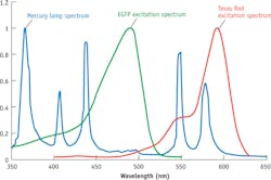
Of course, a source must cover the important fluorescent probes to generate wide market appeal. But identifying which probes are essential isn't straightforward. Over the years, fluorescence microscopy developed dyes that match the spectral peaks of mercury arc lamps, the light source that traditionally offered the best performance for fluorescence. On the other hand, fluorescent proteins enabled such an array of new research that the market accepted such drawbacks as off-peak (for mercury arc lamps) excitation (see Fig. 1). Now, solid-state systems must provide excellent performance for both categories of dyes to be successful in the marketplace. Therefore, it is safe to say that a broad spectrum source must provide coverage from the near-UV to the far-red.Optical limitations of compound research microscopes-such as those found in most cell biology, molecular biology, and physiology labs-challenges the design of light sources. Such microscopes use an objective lens to illuminate the sample with excitation light (hence the term epifluorescence). That light passes through an illumination pathway with both aperture and field stops, and optical filters. Generally, microscopes are designed to provide Kohler illumination, where the light source is completely defocused at the sample plane and therefore in focus at the back aperture of the objective. As the light converges to form the image, only rays with half-angles <3.5°–5° are able to reach the sample and produce useful excitation. Because the back aperture of the objective is rarely larger than 10 mm, the image of the source at the back aperture should be about this size to accommodate most objectives. The image size and angular content of the beam at the back aperture are central in thinking about light source design.
Meeting spectral and optical needs
An LED's suitability for fluorescence excitation depends on the amount of light (milliwatts or watts) in the excitation bands of the most common fluorophores. Often, a solid-state source is specified in terms of lumens, color-rendering index, or color temperature, as these measurements are key for most applications. Unfortunately, these specifications collapse the spectrum to a single number, and account for human color perception—thus muddying the waters and forcing source designers to unravel the actual spectral content and radiometric power just to judge the potential value of a candidate LED. Frequently, testing samples is the most efficient approach.
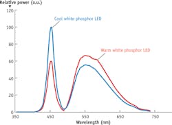
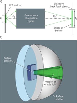
No single LED can cover the entire range needed for broad-spectrum, multipurpose fluorescence excitation. In fact, LED chip technology offers very little in the range of 540–590 nm. In other applications, this is solved by using a blue LED in conjunction with a phosphor to create spectra like those shown in Fig. 2. Though these "white" LEDs can work for fluorescence, they lack important parts of spectrum, so their output must be combined with that of other LEDs. This approach is available in the marketplace, generally using four to seven emitters. Still, the total power available to the sample is limited by the power density of the LED.Figure 3a shows one way to consider the tradeoff between the size of the emitter and the extent to which divergent light can be used for excitation through an objective. An objective lens (depending on manufacturer) on a standard compound microscope can accept fluorescence illumination light with a half-angle of 3.5°–5°. Light beyond this half-angle will not pass through the objective—or if it does, may increase background fluorescence and reduce contrast. The size of the beam is limited by the back aperture of the objective, which is rarely larger than 10 mm. If we take the optical invariant (see Equation 1) at the back focal plane of the objective (Plane 2) and the light source itself (Plane 1), the generic equation in air is:
Consider a 4.25 mm round LED for the emitter, and apply Equation 1 to calculate q1:
Therefore, two parameters of the compound microscope, 3.5°–5° half-angle of illumination and a 10-mm-diameter aperture, limit the usable light diverging from the source to less than 12°. If optics were designed to collect rays from the LED diverging with angles less than 25°, the same approach would recommend an LED with d1= 2 mm. Anything larger is wasted power and extra heat that must be managed.
While the optical invariant approach is an efficient way to highlight the tradeoff, Fig. 3b shows that calculating efficiencies must be more complex. Throughput or total power must be integrated over the whole beam, thus including the area of the emitter and the solid-angle that can be useful, or the use of a quantity that is properly proportional to real power values. (Detailed treatments are available in Illumination Engineering: Design with Nonimaging Optics, Wiley-IEEE Press [2013], by R. John Koshel.)
To avoid a discussion beyond the scope of this article, we take a simplified approach. Equation 2 shows the relation sometimes called throughput, Etendue, or Area-Angle product:
where A is the area of the source and is the solid angle containing the usable rays. A ratio of the usable portion of the emission to the full emission of the LED gives the maximal efficiency possible if for a lossless system. In this case, the important comparison is between the full output of the LED or other source and the output that the microscope can leading to a simple ratio (Equation 3):
Returning to the 4.25 mm LED with 12° of usable half-angle and full hemisphere emission (θtotal = 90°), we have a maximal efficiency of only about 4% if the rest of the system is perfect. This example is, of course, laughable, but it illustrates the importance of a throughput analysis. The 2 mm LED with a 25° angle produces an efficiency of 18%, which can be made to work if the LED's intrinsic brightness is sufficient. A 1-mm-diameter LED with 60° of usable half-angle might be the best balance with a maximum efficiency of 75%, approximately four times the efficiency of an LED with four times the emission area as one would expect.
The implications of the two primary constraints are clear for building a broad-spectrum source for fluorescence excitation. First, the Etendue limitation of the microscope limits the usable size of a surface emitter to about a 1 mm2 with usable emission of 50–60°. Second, a broad-spectrum LED source for fluorescence will require light from near-UV to far-red, including regions that require the use of a phosphor. Third, most white LEDs using a phosphor do not have sufficient spectral content in the near-violet and -UV. A single LED cannot provide all of the light needed.
Solid-state alternative
While the ubiquity of LEDs in applications from homes to headlights makes it easy to forget that other solid-state options exist, super-luminescent diodes and solid-state laser technology span low-cost laser diodes to high-performance diode-pumped lasers. Laser diodes alone cannot produce a continuous broad spectrum, even in combination, and super-luminescent diodes are not practical for several reasons. This leaves the possibility of a hybrid approach to satisfy the needs of fluorescence microscopy.
One approach involves illuminating a phosphor with much higher intensities than can be achieved with an LED. This requires a bright, solid-state source with laser-like output at an acceptable cost. Laser diodes meet these criteria; in fact, multiple laser diodes can be overlapped on a small patch of phosphor to produce an order-of-magnitude increase in incident intensity and a near-point source similar in size to the arc of a discharge lamp.
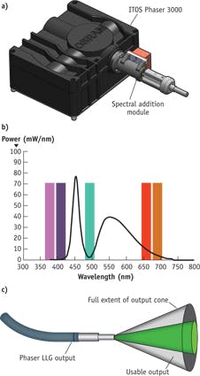
The strategy requires a phosphor (including binder material) that can handle the highly focused power and a thermal strategy adequate to manage the heat. The ITOS PHASER 3000 from OSRAM (see Fig. 4a) is an example of such a source. It uses a bank of blue laser diodes to excite phosphor and produce the greenish-yellow light that cannot be produced by an LED chip. The PHASER uses laser diode light internally only for phosphor excitation, making it the equivalent of a Class I laser product (a class that includes laser printers, for instance) and therefore does not require laser safety precautions for normal operation. To achieve the white spectrum needed, a blue LED adds a lower wavelength component (because this LED is just a blue emitter, the phosphor need not convert any of its power to other wavelengths). Together, the spectra produce a light comparable to a 300W xenon lamp in photometric terms, but with the spectrum of a white LED (see Fig. 4b).The ITOS PHASER system with appropriate optics serves most of the visible range used in fluorescence microscopy, lacking only wavelengths below 430 nm. It is designed for incorporation as a subsystem in a larger system, providing power, cooling, and optical matching to other components. Partner companies 89 North and Chroma Technology have enabled the addition of extra wavelengths with individual LEDs or laser diodes through their Spectral Addition Module (SAM; see Fig. 4a), which effectively augments PHASER's spectrum (see Fig. 4b). PHASER provides the bulk of the power and spectrum, while the SAM adds application-critical wavelengths.
The ITOS PHASER 3000 output is a ø5 mm aperture with a 22° half-angle divergence. If we use the full area and apply Equation 2 to calculate the usable angles diverging from the output, we get ~10° of usable half-angle, which implies a maximum efficiency of 22%. PHASER produces power similar to a 4.25-mm-diameter, phosphor-coated LED, but in a narrower output, resulting in a much better coupling through a microscope (see Fig. 4c). Even a 1 mm white LED, which is about three times as efficient for fluorescence illumination compared to PHASER, produces only 10–15% as much total light. Compared to the best-choice LED, then, PHASER provides 2–4 times more light for fluorescent excitation—demonstrating the potential of a combined approach.
Even better
The requirement of a broad, continuous spectrum and the tight throughput limitations of a compound microscope have made it challenging to adapt LEDs to microscopy, but as technology has advanced and designers have gotten better at managing the output of extended sources, a number of good products have been well received, with calls for even greater brightness and range.
The ITOS PHASER 3000 takes an unusual approach to the general problem of producing a white spectrum from a solid-state source. The powerful output, held in a narrow beam, offers great promise for fluorescence microscopy. The total power, 5 mm aperture, and 22° full output will also serve other light-hungry applications, including fluorescence endoscopy, fluorescence-guided surgery, and whole-animal in vivo imaging.
NOTE
Developer 89 North will release SAM in August 2015 for OEM integration, and will introduce complete light sources based on these technologies in late 2015.
Henry Schek is managing director and director of engineering at 89 North, Burlington, VT; www.89north.com.
